“Lesson 4--Microduino "LED Brightness and PWM"”的版本间的差异
Jasonsheng(讨论 | 贡献) (Created page with "{| style="width: 800px;" |- | ==Objective== LED has only two states on and off in other three experiment, now through button realize LED brightness light gradually and gradual...") |
Jasonsheng(讨论 | 贡献) |
||
| 第1行: | 第1行: | ||
| + | {{Language|Lesson_4--The_button_PWM_control_of_LED_brightness}} | ||
{| style="width: 800px;" | {| style="width: 800px;" | ||
|- | |- | ||
| 第22行: | 第23行: | ||
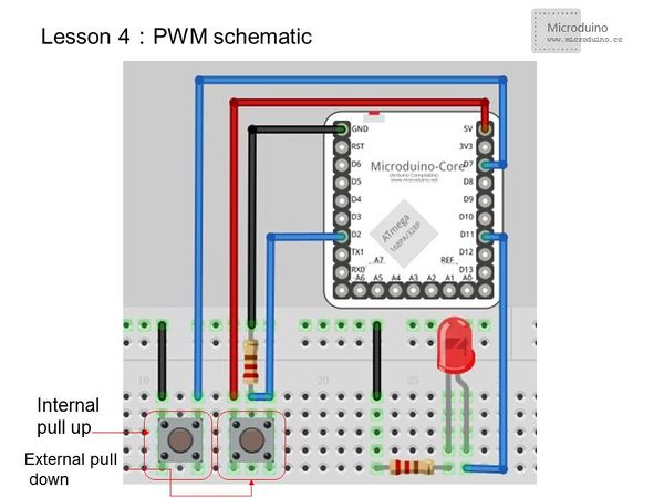
==Experimental schematic== | ==Experimental schematic== | ||
| − | [[File: | + | [[File:pwm schematic.jpg|600px|center|thumb]] |
Buttons are used with internal pull-up and external pull-down, then connect to the digital I/O port D0-D13. | Buttons are used with internal pull-up and external pull-down, then connect to the digital I/O port D0-D13. | ||
PWM must use I/O port D3,D5,56,D9,D10 and D11. | PWM must use I/O port D3,D5,56,D9,D10 and D11. | ||
2014年2月16日 (日) 07:54的版本
| Language | English |
|---|
目录ObjectiveLED has only two states on and off in other three experiment, now through button realize LED brightness light gradually and gradually out That is PWM pulse width modulation. Adjusting digital signal (" 0 ", "1") within a period of time that is the time of the duty ratio, high level "1", the longer and more bright. Detailed information for PWM, please refer to: http://www.geek-workshop.com/thread-125-1-1.html Equipment
Experimental schematicButtons are used with internal pull-up and external pull-down, then connect to the digital I/O port D0-D13. PWM must use I/O port D3,D5,56,D9,D10 and D11. Programint n=0;
void setup ()
{
pinMode(2,INPUT);
pinMode(7,INPUT_PULLUP);//Set to internal pull-up
pinMode(11,OUTPUT);//The PWM only can use I/O port 3、5、11、9、10、11
}
void loop()
{
int up =digitalRead(2); //Read port 2's state
int down = digitalRead(7); //Read port 7's state
if (up==HIGH)
{
n=n+5;
if (n>=255) {
n=255;
} //The max limitation is 255
analogWrite(11,n); //Using PWM control the output of port 11, the range of the variable n is 0-255
delay (300);
}
if (down==LOW)
{
n=n-5;
if (n<=0) {
n=0;
}
analogWrite(11,n); //Using PWM control the output of port 11, the range of the variable n is 0-255
delay (300);
}
}
analogWrite()usage
ResultLeft button to make LED brightness progressively decreasing, and the right button to make LED brightness incremental. Video |
