“模拟电压表”的版本间的差异
(Created page with "{| style="width: 800px;" |- | ==目的== 本教程将教大家如何用Microduino做一个模拟电压表,电压表的读数在Processing中显示。 ==设备== *'''Micr...") |
(→程序) |
||
| (未显示2个用户的8个中间版本) | |||
| 第1行: | 第1行: | ||
| + | {{Language | Simulate_voltage_meter}} | ||
{| style="width: 800px;" | {| style="width: 800px;" | ||
|- | |- | ||
| 第7行: | 第8行: | ||
==设备== | ==设备== | ||
| − | *'''[[Microduino-Core]]''' | + | *'''[[Microduino-Core/zh]]''' |
| − | *'''[[Microduino- | + | *'''[[Microduino-USBTTL/zh]]''' |
| − | |||
*其他硬件设备 | *其他硬件设备 | ||
| 第17行: | 第17行: | ||
**100K欧电阻 一个 | **100K欧电阻 一个 | ||
**跳线 一盒 | **跳线 一盒 | ||
| − | |||
| − | |||
==原理图== | ==原理图== | ||
| 第24行: | 第22行: | ||
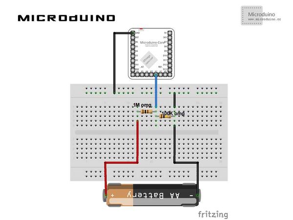
[[File:AnalogVoltmeterConnectionDiagram.jpg|600px|center|thumb]] | [[File:AnalogVoltmeterConnectionDiagram.jpg|600px|center|thumb]] | ||
| − | + | 原理图使用A2,显示电压读数显示在频道一中,一共四个频道分配对应A0,A1,A2,A3你也可以试试。 | |
==程序== | ==程序== | ||
| − | + | [https://github.com/Microduino/Microduino_Tutorials/tree/master/Microduino_Processing/AnalogVoltmeter AnalogVoltmeter] | |
| − | AnalogVoltmeterProcessing | + | [https://github.com/Microduino/Microduino_Tutorials/tree/master/Microduino_Processing/AnalogVoltmeterProcessing AnalogVoltmeterProcessing] |
==调试== | ==调试== | ||
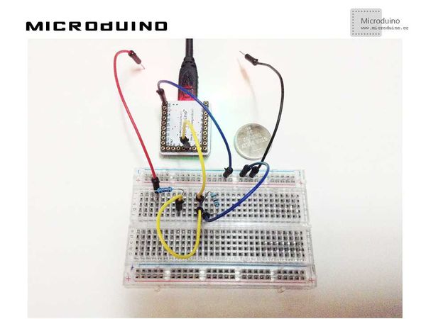
步骤一:按着原理图搭建硬件环境,像这样: | 步骤一:按着原理图搭建硬件环境,像这样: | ||
| − | [[File: | + | [[File:AnalogVoltmeterConnection.jpg|600px|center|thumb]] |
| 第99行: | 第97行: | ||
println(Serial.list()); | println(Serial.list()); | ||
// modify Serial.list()[0] to select correct serial port | // modify Serial.list()[0] to select correct serial port | ||
| − | + | ser_port = new Serial(this, Serial.list()[0], 9600); | |
| − | + | ||
| + | |||
函数说明: | 函数说明: | ||
2014年10月29日 (三) 07:15的最新版本
| Language | English |
|---|
目的本教程将教大家如何用Microduino做一个模拟电压表,电压表的读数在Processing中显示。 设备
原理图原理图使用A2,显示电压读数显示在频道一中,一共四个频道分配对应A0,A1,A2,A3你也可以试试。 程序调试步骤一:按着原理图搭建硬件环境,像这样:
本例需要两端的代码,Processing端和Microduino端 Microduino: //得到电压值后通过串口输出用以Processing端接收 void loop()
{
// take a number of analog samples and add them up
while (sample_count < NUM_SAMPLES) {
// sample each channel A2 to A5
for (l_cnt = 0; l_cnt < 4; l_cnt++) {
sum[l_cnt] += analogRead(A2 + l_cnt);
}
sample_count++;
delay(10);
}
// calculate the voltage for each channel
for (l_cnt = 0; l_cnt < 4; l_cnt++) {
voltage[l_cnt] = ((float)sum[l_cnt] / (float)NUM_SAMPLES * V_REF) / 1024.0;
}
// each voltage is multiplied by the resistor network
// division factor to calculate the actual voltage
voltage[0] = voltage[0] * DIV_1;
voltage[1] = voltage[1] * DIV_2;
voltage[2] = voltage[2] * DIV_3;
voltage[3] = voltage[3] * DIV_4;
// send voltages to Processing application via serial port / USB
// voltage 1 - A (pin A2)
Serial.print("A ");
Serial.print(voltage[0], 1);
Serial.print("V ");
// voltage 2 - B (pin A3)
Serial.print("B ");
Serial.print(voltage[1], 1);
Serial.print("V ");
// voltge 3 - C (pin A4)
Serial.print("C ");
Serial.print(voltage[2], 1);
Serial.print("V ");
// voltage 4 - D (pin A5)
Serial.print("D ");
Serial.print(voltage[3], 1);
Serial.print("V ");
Serial.println("");
delay(10);
// reset count and sums
sample_count = 0;
for (l_cnt = 0; l_cnt < 4; l_cnt++) {
sum[l_cnt] = 0;
}
}
Processing: //得到第一个串口的数据 println(Serial.list()); // modify Serial.list()[0] to select correct serial port ser_port = new Serial(this, Serial.list()[0], 9600);
// 串口事件函数 void serialEvent(Serial p) // 显示频道数和电压值 void voltage (int channel, String volts) //绘制图表轴 void DrawGraphAxis(int pos_x, int pos_y, int width, int height) //绘制图表 void DrawGraph (String voltage, int channel, int pos_x, int pos_y, int scale) // 绘制标尺,单选框 void DrawScaleSelect (int x_pos, int y_pos, int scale)
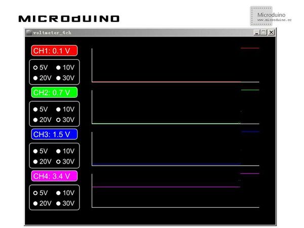
步骤三:下载代码并编译通过。 步骤四:运行后,找个电池之类的,放到上图中红线和黑线之间,看屏幕上的读数。 结果屏幕上第四频道会显示A5 pin的电压读数,像这样:
视频 |


