“Maple Lesson 01 - Blinking LED”的版本间的差异
(→Prerequisites) |
(→Program) |
||
| 第20行: | 第20行: | ||
<source lang="cpp"> | <source lang="cpp"> | ||
| − | int led = | + | int led=4; |
| − | void setup() { | + | void setup() { |
| − | + | // Set up the built-in LED pin as an output: | |
| + | pinMode(led, OUTPUT); | ||
} | } | ||
| + | |||
void loop() { | void loop() { | ||
| − | digitalWrite(led, HIGH); //I/O port | + | digitalWrite(led, HIGH); //I/O port 4 output High. If the connection is high lighted,the LED will light, otherwise extinguished |
| − | delay(1000); // delay 1s | + | delay(1000); // delay 1s |
| − | digitalWrite(led, LOW); //I/O port | + | digitalWrite(led, LOW); //I/O port 4 output Low.If the connection is high lighted,the LED off, otherwise light. |
| − | delay(1000); | + | delay(1000); |
} | } | ||
</source> | </source> | ||
| 第34行: | 第36行: | ||
*Using function millis():Return the number of milliseconds from start running Microduino program to now. | *Using function millis():Return the number of milliseconds from start running Microduino program to now. | ||
<source lang="cpp"> | <source lang="cpp"> | ||
| − | int ledPin= | + | int ledPin=4; |
#define TIME 1000 | #define TIME 1000 | ||
long time1=0,time2=0; | long time1=0,time2=0; | ||
2014年7月15日 (二) 00:48的版本
ObjectiveUsing Microduino-CoreSTM32 to control the on-board LED. Actually you can learn to how to use the Micrduino-CoreSTM32's I/O port. This is a basic skill you should master and for further study. PrerequisitesEquipmentMicroduino-CoreSTM32 is a 32-bit ARM Cortex-M3 development board, based on STMicroelectronics' STM32F103CBT6.
Program
int led=4;
void setup() {
    // Set up the built-in LED pin as an output:
    pinMode(led, OUTPUT);
}

void loop() {
    digitalWrite(led, HIGH); //I/O port 4 output High. If the connection is high lighted,the LED will light, otherwise extinguished
    delay(1000);               // delay 1s
    digitalWrite(led, LOW); //I/O port 4 output Low.If the connection is high lighted,the LED off, otherwise light.
    delay(1000);
}
int ledPin=4;
#define TIME 1000
long time1=0,time2=0;
void setup()
{
  pinMode(ledPin,OUTPUT);
}
void loop()
{
if(millis()<time2+TIME)
{
digitalWrite(ledPin,HIGH);
time1=millis();
}
else
{
digitalWrite(ledPin,LOW);
if(millis()>time1+TIME)
time2=millis();
}
}
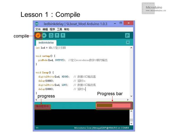
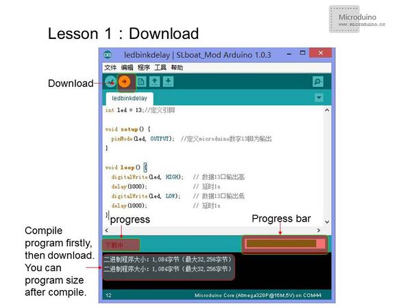
Using function millis () is better than the delay () function, less resource and fewer delays on the system. Download program method
ResultAfter the download, you can see LED flashes once every 1s. Video |

