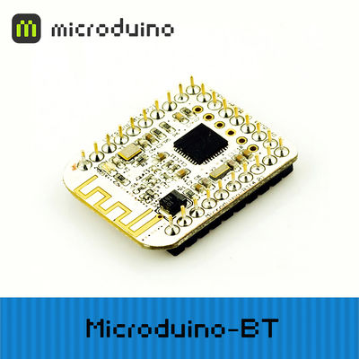
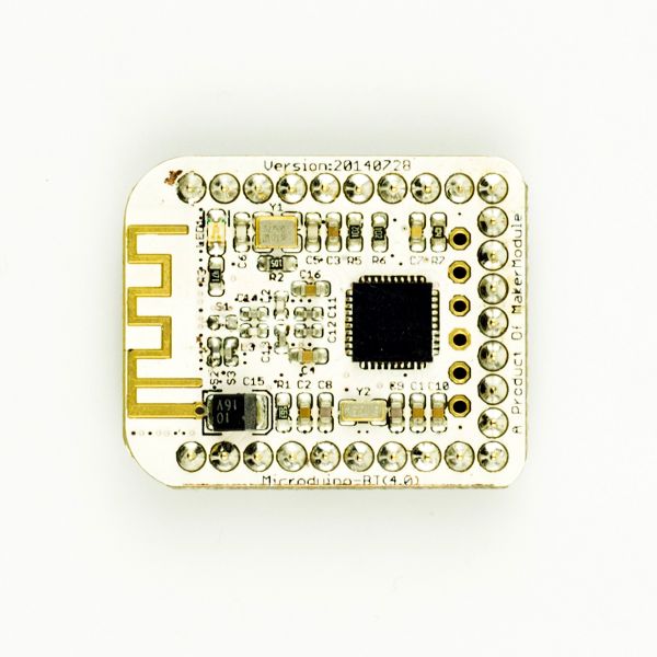
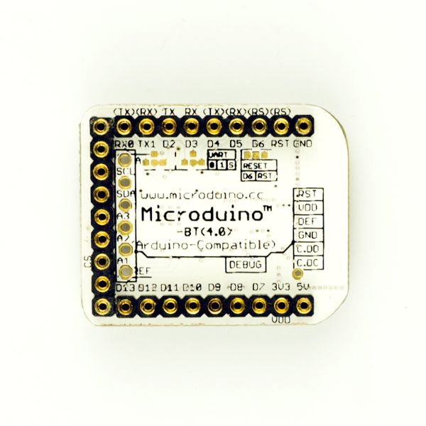
|
|
| (未显示3个用户的18个中间版本) |
| 第7行: |
第7行: |
| | | | |
| | ==特色== | | ==特色== |
| − | *采用 U 型 27 PIN 标准 Microduino 接口,与其他 Microduino 模块堆叠使用; | + | *1)采用 U 型 27 PIN 标准 Microduino 接口,与其他 Microduino 模块堆叠使用; |
| − | *TI CC2541 芯片,低能耗; | + | *2)TI CC2541 芯片,低能耗; |
| − | *支持iBecons模式; | + | *3)支持iBecons模式; |
| − | *多种方式恢复出厂设置, | + | *4)多种方式恢复出厂设置, |
| − | **使用“AT+ RENEW\r\n”命令恢复;
| |
| | **调试引脚的DEF接GND,然后模块上电,此时LED1亮,保持3秒后LED灯闪烁,此时松开DEF,恢复出厂设置成功,可以看到led灯每隔1S闪烁一次。 | | **调试引脚的DEF接GND,然后模块上电,此时LED1亮,保持3秒后LED灯闪烁,此时松开DEF,恢复出厂设置成功,可以看到led灯每隔1S闪烁一次。 |
| − | *有数据掉电保存功能;; | + | *5)有数据掉电保存功能;; |
| − | *支持AT 指令,可根据需要更改串口波特率、设备名称、配对密码等参数,使用灵活; | + | *6)支持AT 指令,可根据需要更改串口波特率、设备名称、配对密码等参数,使用灵活; |
| − | *小巧、便宜、堆叠、开放; | + | *7)小巧、便宜、堆叠、开放; |
| − | *开源的硬件电路设计,与 Arduino 兼容的编程开发环境程; | + | *8)开源的硬件电路设计,与 Arduino 兼容的编程开发环境程; |
| − | *统一的 Microduino 接口规范,和丰富的外围模块,可方便、灵活的与其他符合 Microduino 接口规范的模块、传感器进行快速的连接和扩展; | + | *9)统一的 Microduino 接口规范,和丰富的外围模块,可方便、灵活的与其他符合 Microduino 接口规范的模块、传感器进行快速的连接和扩展; |
| − | *2.54间距的排母接口方便集成到洞洞板。 | + | *10)2.54间距的排母接口方便集成到洞洞板。 |
| | | | |
| | ==规格== | | ==规格== |
| 第46行: |
第45行: |
| | | | |
| | ==文档== | | ==文档== |
| − | Eagle PCB '''[[File:]]'''
| + | 支持AT指令配置/控制, |
| | + | 具体AT指令表见此文档附录:'''[[https://wiki.microduino.cn/images/a/ad/Microduino-BLE.pdf CC2541文档]]''' |
| | | | |
| − | 支持AT指令配置/控制:'''[[File:Microduino-BLE.pdf]]'''
| + | 注意: |
| − | | + | **AT+CLEAR |
| − | ===主要元件===
| + | **AT+TCON |
| − | *cc2541_datasheet:'''[[File:Cc2541.pdf]]''' | + | **AT+RSSI |
| − | | + | **AT+RADD |
| − | ===测试APP===
| + | 均会返回"ERROR",无法使用 |
| − | *APP安装包:'''[[File:BT APP.zip]]''' | |
| − | *APP源码:https://github.com/iascchen/android-microduino | |
| − | | |
| − | | |
| − | 如果玩家想参照github里的android代码开发出自己的app,要注意UUID要和Microduino-BT模块的UUID一致
| |
| − | | |
| − | [[file:Microduino-BT-UUID.png|800px|thumb|center|Microduino-BT-UUID]]
| |
| | | | |
| | ==开发== | | ==开发== |
| − | ===串口通讯要求===
| + | 编程手册:[[Protocol_Reference]] |
| − | *默认的串口配置为:
| |
| − | **波特率 9600
| |
| − | **无校验
| |
| − | **数据位8
| |
| − | **停止位1
| |
| − | *对于Arduino IDE自带串口监视器:
| |
| − | **设置成:“\r\n”、“9600baud”
| |
| − | *对于其他串口调试软件:
| |
| − | **波特率 9600
| |
| − | **无校验
| |
| − | **数据位8
| |
| − | **停止位1
| |
| | | | |
| − | ===PC上位机调试时===
| + | *'''[[【串口通信要求】]]''' |
| − | *直接通过串口调试: | |
| − | **你需要准备'''[[Microduino-USBTTL/zh]]'''
| |
| − | **不要直接将'''[[Microduino-USBTTL/zh]]'''与'''Microduino BLE模块'''叠加
| |
| − | ***因为他们对于Core同属从设备,串口的RX和TX未交差
| |
| − | **将'''[[Microduino-USBTTL/zh]]'''与'''Microduino BLE模块'''两个模块按下表相连。
| |
| − | {|class="wikitable"
| |
| − | |-
| |
| − | |Microduino-BLE||Microduino-USBTTL
| |
| − | |-
| |
| − | |D0||D1
| |
| − | |-
| |
| − | |D1||D0
| |
| − | |-
| |
| − | |3V3 ||3V3
| |
| − | |-
| |
| − | |GND ||GND
| |
| − | |-
| |
| − | |}
| |
| | | | |
| − | ===用USBTTL、Core下载、调试程序时=== | + | ===蓝牙通信程序(通用)=== |
| − | *默认串口跳线RX(D4)、TX(D5),可调用SoftwareSeria库来解决: | + | *请根据模块上的标识选择代码中的通信端口,示例程序中通信端口为D4,D5 |
| − | *玩家自己改动模块背面的跳线:切断两组焊盘中间的连线,将焊盘中间与D2、D3(或者RX0、TX1)焊上即可,参考引脚规则图。 | + | *程序:可将如下程序直接复制到Microduino-IDE中并下载到模块上 |
| − | **若采用了改跳线的方法,可将Microduino BT与Core的串口连接由TX-D4、RX-D5改成:
| |
| − | ***TX-D2、RX-D3(相对Core+的Serial1)
| |
| − | ***TX-RX0、RX-TX1(这时候串口会冲突,不能直接叠加下载程序)
| |
| − | | |
| − | | |
| − | *程序
| |
| | <source lang="cpp"> | | <source lang="cpp"> |
| − | //使用其他软串口用SoftwareSerial
| |
| | #include <SoftwareSerial.h> | | #include <SoftwareSerial.h> |
| − | SoftwareSerial mySerial(4, 5);
| |
| | | | |
| − | #define my_Serial mySerial //使用软串口4,5
| + | String item; |
| − | //#define my_Serial Serial1
| |
| − | String msg = ""; //定义一个字符串 | |
| | | | |
| − | void setup()
| + | String currentInfo=""; |
| − | {
| |
| − | // 初始化蓝牙通信波特率
| |
| − | my_Serial.begin(9600);
| |
| − | // 初始化串口监视器通信波特率
| |
| − | Serial.begin(9600);
| |
| − | }
| |
| − | void loop()
| |
| − | {
| |
| − | //每收到一次信号,向通信另一端反馈一次
| |
| − | if (my_Serial.available() > 0) //如果串口有数据输入
| |
| − | {
| |
| − | msg = my_Serial.readStringUntil('\n'); //获取换行符前所有的内容
| |
| − | Serial.println(msg); //在串口监视器显示收到的msg中的字符串
| |
| − | my_Serial.println("^_^ Hello,Microduino!"); //向蓝牙通信的另一端发送数据
| |
| − | }
| |
| − | }
| |
| − | </source>
| |
| − | | |
| − | ===与Android设备通信===
| |
| − | *系统要4.3以上的手机才能与microduino-BT模块通讯。
| |
| − | *下载Android的通讯软件,安装到手机上。
| |
| − | [[File:ble-serial.gif|200px|center]]
| |
| − | |-
| |
| − | |
| |
| − | 步骤一:将程序下载到Microduino里;
| |
| − | |-
| |
| − | |
| |
| − | [[File:ble-Download2.png|600px|center|thumb|Download]]
| |
| − | | |
| − | 步骤二:开始设置Android设备,打开Android设备的蓝牙功能,打开App,并在电脑IDE端打开串口监视器;
| |
| − | | |
| − | 步骤三:点击App右上方SCAN按钮,这是用来搜索周围蓝牙接入点的,点击SCAN后会显示周围的蓝牙设备。
| |
| − | 点击对应的Microduino蓝牙编号,进入界面等待2-3秒钟,待屏右上角变成“Serial ready”字样,说明手机已经与蓝牙建立了连接.
| |
| − | [[File:202KIT-android-ready.jpg|600px|center|thumb|App—手机App]]
| |
| − | 手机向Microduino发送英文字符,串口监视器中收到手机发送的内容。同时手机接收到了Microduino发送的“^_^ Hello,Microduino!”信息,验证了蓝牙的双向通信功能。
| |
| − | [[File:microduino-android-system5.png|600px|center|thumb|App—串口监视器]]
| |
| − | [[File:202KIT-android-system6.jpg|600px|center|thumb|App—手机App]]
| |
| − | | |
| − | ===与IOS设备通信===
| |
| − | *iPhone4s以上、iPod touch 5以上、iPad 3以上、iPad mini以上;
| |
| − | *前往App Store里下载LightBlue;
| |
| − | | |
| − | [[File:LightBlue.jpg|400px|center|thumb|LightBlue]]
| |
| − | 步骤一:将程序下载到microduino里;
| |
| − | | |
| − | 步骤二:安装“lightblue”,打开软件,开始设置IOS设备,打开IOS设备的蓝牙功能。并在电脑端IDE中打开串口监视器
| |
| − | [[File:LightBlue_on_ble.jpg|400px|center|thumb]]
| |
| − | 步骤三:打开LightBlue;进入的界面是蓝牙设备搜索界面,从“Peripherals Nearby”下的列表中找到Microduino的蓝牙设备,点击该条目使手机与其建立连接;
| |
| − | |-
| |
| − | |
| |
| − | [[File:ble-Connection.jpg|400px|center|thumb|Connection1]]
| |
| − | 连接后进入页面如下:
| |
| − | [[File:ble-Connection1.jpg|400px|center|thumb|Connection2]]
| |
| − | | |
| − | 步骤四:选择并点击Characteristic6,观察屏幕右上方的编码格式,默认为Hex 16进制编码,如果要显示字符串请点击Hex所在的按钮并选择UTF-8编码格式,之后点击“Listen for notifications”使手机进入监听状态。
| |
| − | [[File:ble-Connection5.jpg|400px|center|thumb]]
| |
| − | | |
| − | 步骤六:点击“Write new value”,弹出文本编辑界面
| |
| − | [[File:ble-Connection2.jpg|400px|center|thumb]]
| |
| − | 自定义输入一个英文和数字组成的字符串,观察手机和串口的显示结果
| |
| | | | |
| − | [[File:ble-Connection3.jpg|400px|center|thumb]]
| + | SoftwareSerial mySerial(4, 5); //根据实际模块上的跳线,选择对应端口 |
| − | [[File:ble-Connection4.jpg|400px|center|thumb]]
| |
| − | 可以从图中看到串口收到了手机发送的数据“12345”,手机端也收到了蓝牙返回的数据“bluetooth respond”,说明蓝牙双向通信是畅通的。
| |
| | | | |
| − | ===与MAC设备通信===
| + | #define my_Serial mySerial |
| − | mac蓝牙无法直接与BT搜索连接,需要借助Light Blue来开发。下载
| |
| − | *将Microduino-Core与BT模块连接到电脑,下载同样的代码。
| |
| − | *打开Arduino串口监视器,再打开Light Blue软件,可以发现识到Microduino设备。
| |
| − | [[File:ble-Connection5.png|400px|center]]
| |
| − | *点击Microduino可以和蓝牙连接,连接成功后可以看到串口监视器打印出Connected。同时也可以看到蓝牙指示灯微闪(频率变快,亮度变低)。
| |
| − | [[File:ble-Connection6.png|400px|center]]
| |
| − | *按下图选择,然后向BT模块发送信息,例如:mCookie。
| |
| − | [[File:ble-Connection7.png|800px|center]]
| |
| − | *可以看到串口监视器打印出Microduino。
| |
| − | [[File:ble-Connection8.png|400px|center]]
| |
| − | | |
| − | ==扩展==
| |
| − | ===使用AT查看或更改BT的参数===
| |
| − | *AT指令配置/控制文档:'''[[File:Microduino-BLE.pdf]]'''
| |
| − | *程序
| |
| − | <source lang="cpp">
| |
| − | //使用其他软串口用SoftwareSerial
| |
| − | //#include <SoftwareSerial.h>
| |
| − | //SoftwareSerial mySerial(4, 5); // RX, TX
| |
| − | | |
| − | //#define my_Serial mySerial
| |
| − | #define my_Serial Serial1 //定义CoreUSB与BT串口
| |
| | | | |
| | void setup() | | void setup() |
| − | {
| |
| − | Serial.begin(9600);//串口监视器通讯波特率
| |
| − | my_Serial.begin(9600);//BT通讯波特率
| |
| − | }
| |
| | | | |
| − | void loop()
| |
| | { | | { |
| − | if (Serial.available())//监视到串口监视器的数据 | + | item = ""; |
| − | my_Serial.write(Serial.read());//将数据写入BT
| |
| − | if (my_Serial.available())//监视到BT串口的数据
| |
| − | Serial.write(my_Serial.read());//将数据在串口监视器打印出来
| |
| − | }
| |
| − | </source>
| |
| − | *下载程序
| |
| − | **将mCookie-BT与mCookie-CoreUSB两个模块叠在一起,将USB线插入mCookie-CoreUSB的插孔,另一端连接电脑USB插口;
| |
| − | **启动Arduino IED,将上面程序复制到IDE中;
| |
| − | **在工具(tools)->板卡(Board)中选择Microduino CoreUSB,并在工具(tools)->串口(Serial)中选择对应的串口号;
| |
| − | **点击IDE左上角的编译(√)按钮对程序进行编译,编译结束后点击下载(->)按钮将程序烧录到板子中;
| |
| − | *打开串口监视器,设置成:“\r\n”、“9600baud”。
| |
| − | [[File:ble-Serial.jpg|600px|center|thumb|Serial]]
| |
| − | *在串口监视器中输入指定指令,可以看到返回结果,参考文档可更改BT的参数。
| |
| − | [[File:ble-AT.jpg|600px|center|thumb|AT]]
| |
| | | | |
| − | 使用软串口通讯程序:
| |
| − | <source lang="cpp">
| |
| − | //使用其他软串口用SoftwareSerial
| |
| − | #include <SoftwareSerial.h>
| |
| − | SoftwareSerial mySerial(4, 5);//根据选择的串口,选择对应的端口号(2,3)或(4,5)
| |
| − |
| |
| − | #define my_Serial mySerial
| |
| − |
| |
| − | String msg = "";
| |
| − |
| |
| − | void setup()
| |
| − | {
| |
| − | // 初始化蓝牙通信波特率
| |
| | my_Serial.begin(9600); | | my_Serial.begin(9600); |
| − | // 初始化串口监视器通信波特率
| |
| − | Serial.begin(9600);
| |
| − | }
| |
| − | void loop()
| |
| − | {
| |
| − | //每收到一次信号,向通信另一端反馈一次
| |
| − | if (my_Serial.available() > 0) //如果串口有数据输入
| |
| − | {
| |
| − | msg = my_Serial.readStringUntil('\n'); //获取换行符前所有的内容
| |
| − | Serial.println(msg); //在串口监视器显示收到的msg中的字符串
| |
| − | my_Serial.println("bluetooth respond"); //向蓝牙通信的另一端发送数据
| |
| − | }
| |
| − | }
| |
| − | </source>
| |
| − |
| |
| − | ===引脚说明===
| |
| | | | |
| − | :[[file:Microduino-BT-1Big2.jpg|800px|thumb|center|Microduino-BT]]
| |
| − | <br style="clear: left"/>
| |
| − | :[[file:Microduino-BT-2Big1.jpg|800px|thumb|center|Microduino-BT]]
| |
| − | <br style="clear: left"/>
| |
| − |
| |
| − | {|class="wikitable"
| |
| − | ! rowspan="1" | HM-10模块引脚名 || Microduino引脚 || 功能
| |
| − | |-
| |
| − | | TX|| RX0(orD2/D4) || 模块串口发送脚(TTL电平),可接单片机的RXD
| |
| − | |-
| |
| − | | RX || TX1(orD3/D5) || 模块串口接收脚(TTL电平),可接单片机的TXD
| |
| − | |}
| |
| − |
| |
| − | ==应用==
| |
| − | ===程序下载===
| |
| − | 测试程序:'''[[File:BLE debug uart1.zip]]''','''[[File:BLE LightBlue time.zip]]'''
| |
| − |
| |
| − |
| |
| − | BT模块发送示例:
| |
| − | <source lang="cpp">
| |
| − |
| |
| − | #include <SoftwareSerial.h>
| |
| − |
| |
| − | SoftwareSerial mySerial(4, 5); //RX,TX
| |
| − |
| |
| − | #define my_Serial mySerial //core
| |
| − | //#define my_Serial Serial1 //Core+
| |
| − |
| |
| − | String currentInfo="";
| |
| − |
| |
| − | void setup() {
| |
| | Serial.begin(9600); | | Serial.begin(9600); |
| | | | |
| − | my_Serial.begin(9600);
| |
| − |
| |
| − | delay(200); // a 2 seconds delay while we position the solar panel
| |
| | } | | } |
| | | | |
| − | void loop() { | + | void loop() |
| | | | |
| − | my_Serial.println("111");
| + | { |
| − | delay(500);
| + | if (my_Serial.available() > 0) { |
| − | my_Serial.println("222");
| |
| − | delay(500);
| |
| − | my_Serial.println("333"); | |
| − | delay(500);
| |
| | | | |
| − | }
| + | currentInfo = my_Serial.readStringUntil('\n'); |
| | | | |
| − | </source>
| + | Serial.println(currentInfo); |
| − | | + | } |
| − | | + | if (Serial.available() > 0) { |
| − | BT模块接收示例:
| |
| − | | |
| − | <source lang="cpp">
| |
| − | | |
| − | #include <SoftwareSerial.h>
| |
| | | | |
| − | SoftwareSerial mySerial(4, 5); //RX,TX
| + | item = Serial.readString(); |
| | | | |
| − | #define my_Serial mySerial //core
| + | my_Serial.println(item); |
| − | //#define my_Serial Serial1 //Core+
| |
| − | | |
| − | String currentInfo="";
| |
| − | | |
| − | void setup() {
| |
| − | Serial.begin(9600);
| |
| − | | |
| − | my_Serial.begin(9600);
| |
| − | | |
| − | delay(200); // a 2 seconds delay while we position the solar panel
| |
| − | }
| |
| − | | |
| − | void loop() {
| |
| − | | |
| − | | |
| − | if (my_Serial.available() > 0) {
| |
| − | currentInfo = my_Serial.readStringUntil('\n'); | |
| − | Serial.println(currentInfo);
| |
| − | if(currentInfo=="ERROR"||currentInfo=="Connected") {
| |
| − | return;
| |
| − | }
| |
| | | | |
| | + | Serial.println(item); |
| | } | | } |
| − |
| |
| | } | | } |
| − |
| |
| | </source> | | </source> |
| | | | |
| − | ===通过CoreUSB对Shield BT4.0进行串口调试=== | + | ===与IOS设备通信=== |
| − | *所需要准备的硬件有:Microduino CoreUSB、Microduino BT; | + | *'''[[【使用LightBlue通信】]]''' |
| − | *所需要准备的软件有:Arduino IDE(1.0版本以上)、Microduino提供的测试程序(Arduino端); | + | *'''[[【使用mRobot通信制作小车】]]''' |
| − | **其他条件:玩家已经改过模块背面跳线,使得串口改到RXO(D0)、TX1(D1);(因为CoreUSB可以利用USB模拟出串口0(Serial),而RX0、TX1是CoreUSB的串口1(Serial1)); | + | *'''[[【使用mDock通信制作多样应用】]]''' |
| − | *启动Arduino IED,打开Microduino提供的测试程序,板卡选择Microduino CoreUSB,直接下载即可;
| |
| − | *检测串口通讯是否正常:
| |
| − | **打开对应串口监视器后,发送大写“AT”(AT 后要有\r\n 符号),若返回“OK”,说明配置成功。
| |
| | | | |
| − | ===通过Core+的uart1对Microduino BT进行串口调试=== | + | ===与MAC设备通信=== |
| − | *所需要准备的硬件有:Microduino USBTTL、Microduino Core+、Microduino BT; | + | *'''[[【与MAC设备通信的方法】]]''' |
| − | *所需要准备的软件有:Arduino IDE(1.0版本以上)、Microduino提供的测试程序(Arduino端);
| |
| − | *其他条件:玩家已经改过模块背面跳线,使得串口改到D2、D3;
| |
| − | *启动Arduino IED,打开Microduino提供的测试程序,板卡选择Microduino Core+ (Atmega644P@16M,5V),直接下载即可;
| |
| − | *检测串口通讯是否正常:
| |
| − | **打开对应串口监视器后,发送大写“AT”(AT 后要有\r\n 符号),若返回“OK”,说明配置成功。
| |
| | | | |
| − | ==[[两个Microduino BT互相通信]]== | + | ==扩展== |
| | + | *'''[[【使用AT指令修改蓝牙设置】]]''' |
| | + | *'''[[【修改跳线以更改串口引脚】]]''' |
| | | | |
| − | ==[[Microduino BT串口透传数据到IOS设备]]==
| + | 如果玩家想参照github里的android代码开发出自己的app,要注意UUID要和Microduino-BT模块的UUID一致 |
| − | | |
| − | ===注意:如果使用Android设备调试,系统要4.3以上的才能检测到Microduino BT模块。===
| |
| − | | |
| − | 通讯源代码参考:https://github.com/iascchen/android-microduino
| |
| − | | |
| − | ===Microduino-Shield BT4.0 简单测试===
| |
| − | *[http://viewc.com/p/296 Microduino-Shield BT4.0 简单测试] 来自 @颜火山
| |
| | | | |
| | '''其它应用:''' | | '''其它应用:''' |


