“Microduino-NEO-6M”的版本间的差异
(→Development) |
|||
| (未显示2个用户的2个中间版本) | |||
| 第88行: | 第88行: | ||
* Make sure the +3.3 v power supply current can reach 200ma, not recommended use FT232R debugging directly, because FT232R's output +3.3 v current is too small. | * Make sure the +3.3 v power supply current can reach 200ma, not recommended use FT232R debugging directly, because FT232R's output +3.3 v current is too small. | ||
| − | === | + | * We suggest to use Microduino Core 32u4 to debug this BT module: |
| − | * | + | ** 32u4 module can use the USB to simulate the serial 0, and BT uses the 32u4's serial 1 (RX0,TX1), so you don't need change the existing jumper (RX0,TX1) and it won't impact the program downloading and serial's function. |
| − | * | + | * Microduino Shield BT4.0 uses the default serial RX0,TX1 to communicate with Core module, so can connect with Microduino FT232 directly. |
| + | |||
| + | ===Use PC to debug=== | ||
| + | * Use serial directly: | ||
| + | ** No need superimpose the FT232 directly, cross connect the FT232 and NEO-6M's RX0,TX1. | ||
| + | |||
| + | ===Use FT232R、Core download and debug=== | ||
| + | *Use default jumper (RX0、TX1): | ||
| + | **Unplug the Microduino NEO-6M during download program; | ||
| + | *If you want to change the jumper cables to meet your requirement:cut the connection between two intermediate of the pad and RX0/TX1, and then connect them to D2, D3. | ||
| + | **If changed the jumper, need the change the serial connection between Microduino NEO-6M and Core module, change the connection "TX-RX0、RX-TX1" to following: | ||
| + | ***TX-D2、RX-D3 (For Core+'s Serial1) | ||
| + | |||
| + | ===Arduino library and supported package=== | ||
| + | *【Adafruit_GPS library'''[https://github.com/adafruit/Adafruit-GPS-Library github download ]''' 】 | ||
| + | *【U8glib library'''[http://code.google.com/p/u8glib/ google download ]''' 】 | ||
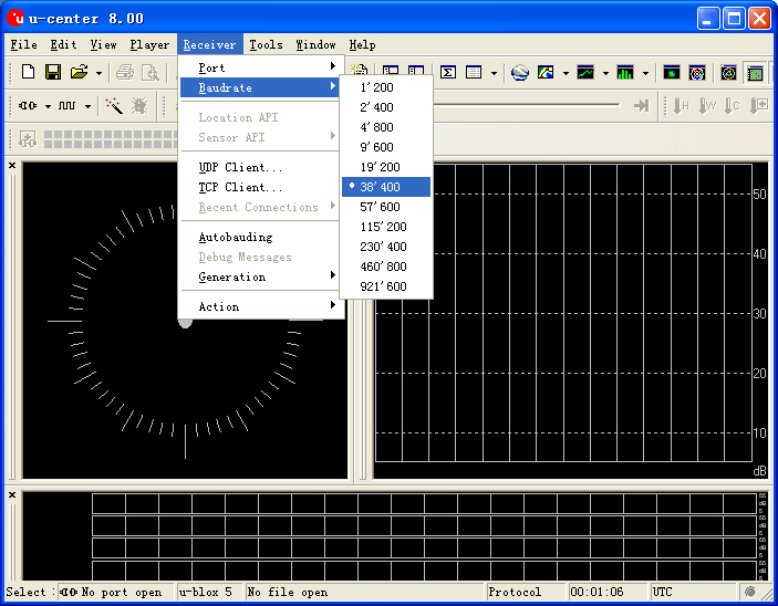
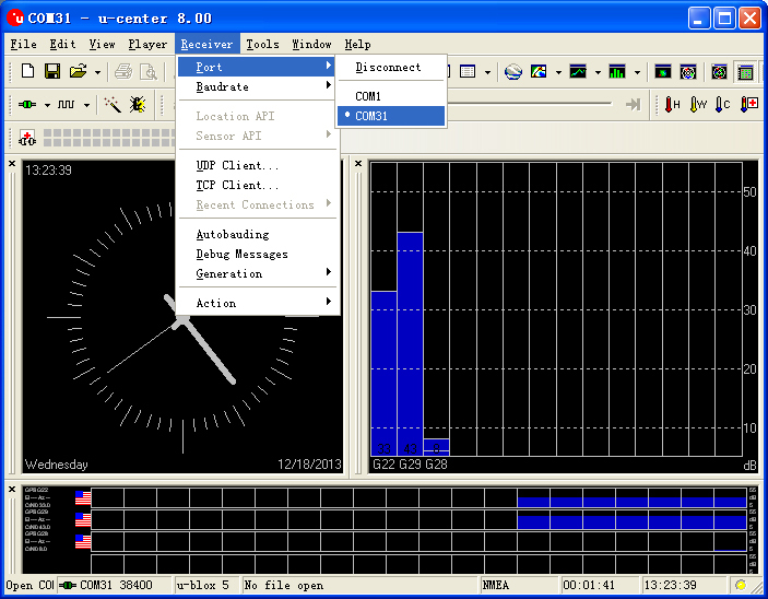
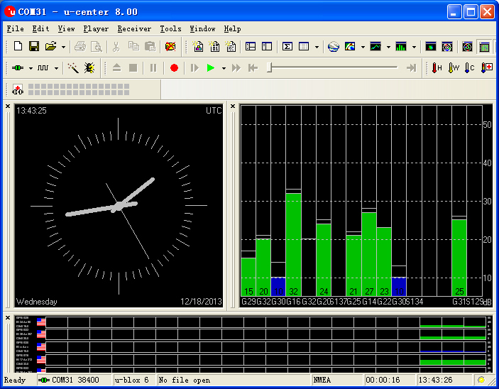
*[http://www.u-blox.com/en/evaluation-tools-a-software/u-center/u-center.html u-center-8.0] | *[http://www.u-blox.com/en/evaluation-tools-a-software/u-center/u-center.html u-center-8.0] | ||
| 第110行: | 第125行: | ||
**Flicker,(100ms off,900ms on),indicates that module has achieved position successfully. | **Flicker,(100ms off,900ms on),indicates that module has achieved position successfully. | ||
*Easy to identify the state of module by PPS indicator. | *Easy to identify the state of module by PPS indicator. | ||
| − | |||
==Application== | ==Application== | ||
| 第139行: | 第153行: | ||
**Using the jumper cable cross connect the RX0/TX1 for FT232 and NEO-6M, that is the RX0 of NEO-6M connects to the TX1 of FT232, and the TX1 of NEO-6M connects to RX0 of FT232. | **Using the jumper cable cross connect the RX0/TX1 for FT232 and NEO-6M, that is the RX0 of NEO-6M connects to the TX1 of FT232, and the TX1 of NEO-6M connects to RX0 of FT232. | ||
**Connect the 3V3 pin of NEO-6M module to 3V3 pin of FT232, and connects the GND together. | **Connect the 3V3 pin of NEO-6M module to 3V3 pin of FT232, and connects the GND together. | ||
| + | |||
| + | [[File:Neo-6m debugging.jpg|thumb|400px|center|crossover configuration]] | ||
| + | |||
2. Use the changed jumper mode | 2. Use the changed jumper mode | ||
If you have changed the jumper as upper described, you can supperipose FT232, NEO-6M and Core module together, then connect to PC to debug directly. | If you have changed the jumper as upper described, you can supperipose FT232, NEO-6M and Core module together, then connect to PC to debug directly. | ||
| + | |||
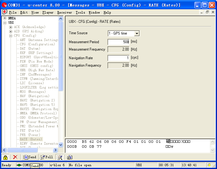
====Use u-center configuration module to update rage==== | ====Use u-center configuration module to update rage==== | ||
*Firstly, place the Microduino NEO-6M into an open area, and then connects to PC by Microduino FT232R; | *Firstly, place the Microduino NEO-6M into an open area, and then connects to PC by Microduino FT232R; | ||
2014年5月10日 (六) 13:18的最新版本
| Language | English |
|---|
|
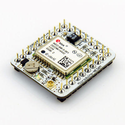
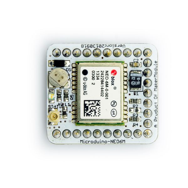
Microduino-NEO module maybe the most beautiful GPS module that you've seen. Its core module use UBLOX NEO-6M, high sensitivity, update rate up to 5Hz, using mini ceramic antenna with IPEX interface, and build-in a rechargeable battery backup. 目录Feature
| |||||||||||||||||||||||||||||
Specifications
Pin Description
文件:NEO6M-Pinout-2.jpg Microduino-NEO6M-Pinout 文件:NEO6M-Pinout-1.jpg Microduino-NEO6M-Pinout DocumentEagle PCB 文件:Microduino-NEO6M.zip
Main components
Development
Use PC to debug
Use FT232R、Core download and debug
Arduino library and supported package
How to use the library
PPS State indicator
ApplicationDownload programTesp Program:文件:Program Test NEO-6M.zip Test Microduino NEO-6M using FT232 and core module
Test Mocroduino NEO-6M using PCConnection methodThere are two connection methods: 1. Use the default pin (RX0、TX1):
文件:Neo-6m debugging.jpg crossover configuration 2. Use the changed jumper mode If you have changed the jumper as upper described, you can supperipose FT232, NEO-6M and Core module together, then connect to PC to debug directly. Use u-center configuration module to update rage
BugHistoryPicture
Video |
