|
|
| (未显示3个用户的34个中间版本) |
| 第2行: |
第2行: |
| | {| style="width: 800px;" | | {| style="width: 800px;" |
| | | | | | |
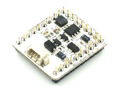
| − | [[File:Microduino-bm-rect.jpg|400px|thumb|right|Microduino-BM]] | + | [[File:Microduino-bm-new.jpg|400px|thumb|right|Microduino-BM]] |
| | | | |
| | | | |
| − | Microduino-BM是一款集成了单节锂电池microusb充电管理、电池欠压指示灯,充电指示灯,和电压输出指示灯、升压到5V输出、LDO到3.3V输出的放电管理模块。 | + | Microduino-BM_Li-ion是一款单节锂电池升压到5V输出、LDO到3.3V输出的放电管理模块。需要配合[[Microduino Module BM Shield/zh]]来使用。 |
| | + | |
| | + | 原模块参考[[Microduino-Module_BM_Li-ion(old)/zh]]。 |
| | | | |
| | | | |
| | ==特色== | | ==特色== |
| − | *支持UPS; | + | *支持UPS(需配合[[Microduino Module BM Shield/zh]]); |
| − | *充放电管理、电量检测、电压输出指示、5v升压、3.3v LDO高度集成; | + | *电量检测、5v升压、3.3v LDO高度集成; |
| | *小巧、便宜、堆叠、开放; | | *小巧、便宜、堆叠、开放; |
| | *统一的 Microduino 接口规范,和丰富的外围模块,可方便、灵活的与其他符合 Microduino 接口规范的模块、传感器进行快速的连接和扩展; | | *统一的 Microduino 接口规范,和丰富的外围模块,可方便、灵活的与其他符合 Microduino 接口规范的模块、传感器进行快速的连接和扩展; |
| 第17行: |
第19行: |
| | ==规格== | | ==规格== |
| | *首先来看看本模块的接口: | | *首先来看看本模块的接口: |
| − | **一个两档拨档开关,用来控制是否输出电压(5V和3.3V);
| + | **一个1.27间距的4Pin接口("VUSB","SWI","BAT"以及"GND"); |
| − | **一个microusb接口,用来供电或给锂电池充电;
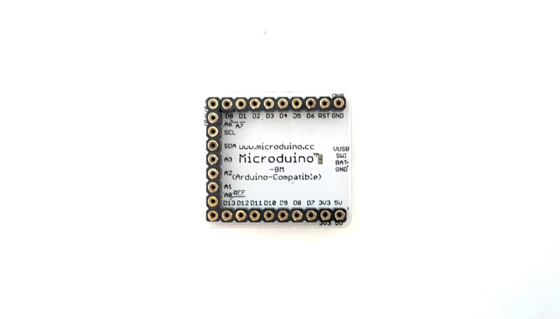
| + | **UPIN27上起作用的接口有5V、3V3、GND;BM上的模拟电压检测可以在A6和A7之间进行选择,可以利用mcu检测电池的电压来判断电池的电量,不要依靠保护电路保护电池,保护电路只是极端情况下才起作用。 |
| − | **一个1.27间距的电池接口(“+”接电池正极,“-”接电池负极); | |
| − | **UPIN27上起作用的接口有5V、3V3、GND;BM上的模拟电压检测可以在A6和A7之间进行选择,数字低电压输出到D2接口,可以利用mcu检测电池的电压来判断电池的电量,不要依靠保护电路保护电池,保护电路只是极端情况下才起作用。 | |
| | | | |
| | '''引脚说明''' | | '''引脚说明''' |
| | | | |
| − | [[file:Micrmodule-BMPin1.jpg|800px|thumb|center|pinout]] | + | [[file:Microduino-bm-new.jpg|800px|thumb|center|pinout]] |
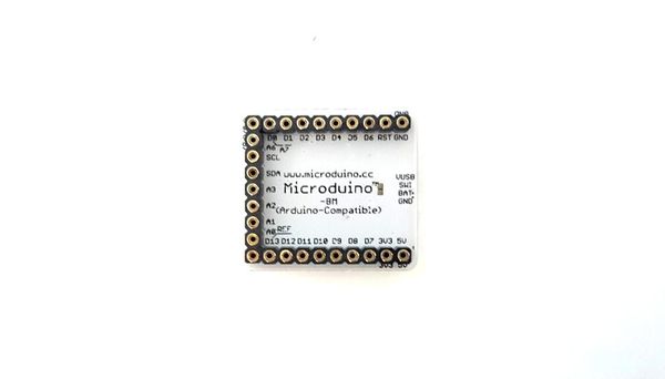
| − | [[file:Micrmodule-BMPin2.jpg|800px|thumb|center|pinout]] | + | [[file:Microduino-bm-new-2.jpg|800px|thumb|center|pinout]] |
| | | | |
| | + | ===供电=== |
| | + | *当接上Microduino Module BM Shield时且处于供电状态,5v提供1a的电力输出,3.3v提供700ma的电力输出。 |
| | | | |
| − | ===充电=== | + | ==文档== |
| − | *插上microusb,给锂电池以600ma的电流进行充电,此时 5v和3.3v的输出由mcirousb供给;
| + | PCB ''[[File:Battery Mange.rar]]'' |
| − | *指示灯(CHAG)充电时候亮,充满了就会灭。
| |
| − | ===放电===
| |
| − | *插上microusb的时候,5v和3.3v电压由mcirousb供给,否则 5v和3.3v电压由锂电池提供,同时你需要将控制电源输出的开关拨到ON,才能提供电源;如果没有启动请用mcirousb充电接入激活下。
| |
| − | *有电源输出,指示灯(OUT)点亮,否则熄灭。
| |
| − | *5v提供1a的电力输出,3.3v提供700ma的电力输出。
| |
| | | | |
| − | ===电池低电压保护=== | + | ===主要元件=== |
| − | {|class="wikitable"
| + | *MOS管:AO3407 '''[[File:AO3407.pdf]]''' |
| − | |-
| |
| − | | 欠压提示电压|| 3.60V
| |
| − | |-
| |
| − | | 低电压保护电压||2.40V
| |
| − | |-
| |
| − | | 电压回升指示灯熄灭电压||3.71V
| |
| − | |}
| |
| | | | |
| − | 欠压指示灯(LOW)在3.60V以下时亮起,当电压持续降低电压到2.40V的时候锂电池保护电路动作,切断了锂电池,当给电池充电使电压回升到3.71V时指示灯熄灭。
| + | ==开发== |
| | + | *Microduino Module BM Shield,并接上3.7单节锂电池或接上USB; |
| | + | *用1.27间距的4PIN线连接Microduino Module BM Shield; |
| | + | *电量计算: |
| | + | <source lang="cpp"> |
| | | | |
| − | ===短路保护===
| + | //电压检测引脚,BM Shield默认是A7引脚 |
| − | 锂电池供电的时候5V和3.3V端输出电流到'''1.2A'''时,锂电池保护电路启动,切断锂电电源,当锂电池保护电路启动时直到有mcirousb充电接入激活,才能再次恢复工作。'''用mcirousb供电时候,是没有短路保护和保护措施的,大家使用的时候一定要多加注意。'''
| + | #define PIN_bat A7 //BAT |
| | | | |
| − | ===bm的效率和负载驱动能力===
| + | //MCU工作电压,需要根据情况选择 |
| − | 100ma 5.05v输出:
| + | #define MCU_VOLTAGE 50 |
| − | {|class="wikitable"
| + | //#define MCU_VOLTAGE 33 |
| − | | align="center" style="background:#f0f0f0;"|'''输入电压'''
| |
| − | | align="center" style="background:#f0f0f0;"|'''4.2'''
| |
| − | | align="center" style="background:#f0f0f0;"|'''4'''
| |
| − | | align="center" style="background:#f0f0f0;"|'''3.8'''
| |
| − | | align="center" style="background:#f0f0f0;"|'''3.6'''
| |
| − | | align="center" style="background:#f0f0f0;"|'''3.4'''
| |
| − | | align="center" style="background:#f0f0f0;"|'''3.2'''
| |
| − | | align="center" style="background:#f0f0f0;"|'''3'''
| |
| − | | align="center" style="background:#f0f0f0;"|'''2.8'''
| |
| − | |-
| |
| − | | 输入电流||139||148||156||166||178||190||204||220
| |
| − | |-
| |
| − | | 效率||86.50%||85.30%||85.20%||84.50%||83.40%||83.10%||82.50%||82.00%
| |
| − | |}
| |
| | | | |
| − | 300ma 5.05v输出:
| + | #define _V_max 41 //4.2V |
| − | {| class="wikitable"
| + | #define _V_min 35 //3.7V |
| − | | align="center" style="background:#f0f0f0;"|'''输入电压'''
| |
| − | | align="center" style="background:#f0f0f0;"|'''4.2'''
| |
| − | | align="center" style="background:#f0f0f0;"|'''4'''
| |
| − | | align="center" style="background:#f0f0f0;"|'''3.8'''
| |
| − | | align="center" style="background:#f0f0f0;"|'''3.6'''
| |
| − | | align="center" style="background:#f0f0f0;"|'''3.4'''
| |
| − | | align="center" style="background:#f0f0f0;"|'''3.2'''
| |
| − | | align="center" style="background:#f0f0f0;"|'''3'''
| |
| − | | align="center" style="background:#f0f0f0;"|'''2.8'''
| |
| − | |-
| |
| − | | 输入电流||411||437||460||492||525||570||615||679
| |
| − | |-
| |
| − | | 效率||87.80%||87.10%||86.90%||85.40%||84.70%||82.90%||81.50%||79.70%
| |
| − | |}
| |
| − | 500ma 5.05v输出:
| |
| − | {| class="wikitable"
| |
| − | | align="center" style="background:#f0f0f0;"|'''输入电压'''
| |
| − | | align="center" style="background:#f0f0f0;"|'''4.2'''
| |
| − | | align="center" style="background:#f0f0f0;"|'''4'''
| |
| − | | align="center" style="background:#f0f0f0;"|'''3.8'''
| |
| − | | align="center" style="background:#f0f0f0;"|'''3.6'''
| |
| − | | align="center" style="background:#f0f0f0;"|'''3.4'''
| |
| − | | align="center" style="background:#f0f0f0;"|'''3.2'''
| |
| − | | align="center" style="background:#f0f0f0;"|'''3'''
| |
| − | | align="center" style="background:#f0f0f0;"|'''2.8'''
| |
| − | |-
| |
| − | | 输入电流||706||746||800||863||938||1028||1157
| |
| − | |-
| |
| − | | 效率||85.20%||84.60%||83.10%||81.30%||79.20%||76.80%||72.70%||
| |
| − | |}
| |
| − | 700ma 5.05v输出:
| |
| − | {| class="wikitable"
| |
| − | | align="center" style="background:#f0f0f0;"|'''输入电压'''
| |
| − | | align="center" style="background:#f0f0f0;"|'''4.2'''
| |
| − | | align="center" style="background:#f0f0f0;"|'''4'''
| |
| − | | align="center" style="background:#f0f0f0;"|'''3.8'''
| |
| − | | align="center" style="background:#f0f0f0;"|'''3.6'''
| |
| − | | align="center" style="background:#f0f0f0;"|'''3.4'''
| |
| − | | align="center" style="background:#f0f0f0;"|'''3.2'''
| |
| − | | align="center" style="background:#f0f0f0;"|'''3'''
| |
| − | | align="center" style="background:#f0f0f0;"|'''2.8'''
| |
| − | |-
| |
| − | | 输入电流||1025||1104||1189||1313||1510
| |
| − | |-
| |
| − | | 效率||82.10%||80.00%||78.20%||74.80%||68.90%||||||
| |
| − | |}
| |
| − | 1A 5.05v输出:
| |
| − | {| class="wikitable"
| |
| − | | align="center" style="background:#f0f0f0;"|'''输入电压'''
| |
| − | | align="center" style="background:#f0f0f0;"|'''4.2'''
| |
| − | | align="center" style="background:#f0f0f0;"|'''4'''
| |
| − | | align="center" style="background:#f0f0f0;"|'''3.8'''
| |
| − | | align="center" style="background:#f0f0f0;"|'''3.6'''
| |
| − | | align="center" style="background:#f0f0f0;"|'''3.4'''
| |
| − | | align="center" style="background:#f0f0f0;"|'''3.2'''
| |
| − | | align="center" style="background:#f0f0f0;"|'''3'''
| |
| − | | align="center" style="background:#f0f0f0;"|'''2.8'''
| |
| − | |-
| |
| − | | 输入电流||1622||1842
| |
| − | |-
| |
| − | | 效率||74.10%||68.50%||||||||||||
| |
| − | |}
| |
| | | | |
| − | [[file:Micrmodule-BM-Analysis.jpg|thumb|600px|center|image]]
| + | #define _V_fix 0.2 //fix battery voltage |
| | + | #define _V_math(Y) (_V_fix+((Y*analogRead(PIN_bat)/1023.0f)/(33.0f/(51.0f+33.0f)))) |
| | | | |
| − | 从数据和图表中可以看出来,bm的5v输出在低功率输出和高功率输出的时候都保持了不错的转换效率,负载驱动能力5v的峰值可以达到1A。3.3v的转换效率取决于1117芯片,转换效率应该在60%左右,负载驱动能力在峰值达到600ma。
| + | uint8_t batVoltage() { |
| | + | return constrain(_V_math(MCU_VOLTAGE), _V_min, _V_max); |
| | + | } |
| | | | |
| − | ===系统工作的温升===
| + | </source> |
| − | 室温30摄氏度5v输出时模块工作温升:
| |
| − | {| class="wikitable"
| |
| − | | align="center" style="background:#f0f0f0;"|''''''
| |
| − | | align="center" style="background:#f0f0f0;"|'''3分钟'''
| |
| − | | align="center" style="background:#f0f0f0;"|''''''
| |
| − | | align="center" style="background:#f0f0f0;"|''''''
| |
| − | | align="center" style="background:#f0f0f0;"|'''5分钟'''
| |
| − | | align="center" style="background:#f0f0f0;"|''''''
| |
| − | | align="center" style="background:#f0f0f0;"|''''''
| |
| − | | align="center" style="background:#f0f0f0;"|'''10分钟'''
| |
| − | |-
| |
| − | | 电流||300||500||700||300||500||700||300||500||700
| |
| − | |-
| |
| − | | 温度||32||35.8||46||32.7||40||48||32.7||40||51
| |
| − | |}
| |
| − | 室温26摄氏度3.3v输出时模块温升:
| |
| − | {| class="wikitable"
| |
| − | | align="center" style="background:#f0f0f0;"|''''''
| |
| − | | align="center" style="background:#f0f0f0;"|'''3分钟'''
| |
| − | | align="center" style="background:#f0f0f0;"|''''''
| |
| − | | align="center" style="background:#f0f0f0;"|''''''
| |
| − | | align="center" style="background:#f0f0f0;"|'''5分钟'''
| |
| − | | align="center" style="background:#f0f0f0;"|''''''
| |
| − | | align="center" style="background:#f0f0f0;"|''''''
| |
| − | | align="center" style="background:#f0f0f0;"|'''10分钟'''
| |
| − | |-
| |
| − | | 电流||100||300||500||300||500||700||300||500||700
| |
| − | |-
| |
| − | | 温度||27.5||32||40||28.5||35||44||28.5||38||49
| |
| − | |}
| |
| − | | |
| − | ==文档==
| |
| − | Eagle PCB '''[[File:Microduino-BM.zip]]''
| |
| − | | |
| − | ===主要元件===
| |
| − | *芯片:LP2985AIM5X-3.3 '''[[File:LP2985.pdf]]'''
| |
| − | *MOS管:AO3400 '''[[File:AO3400.pdf]]'''
| |
| − | *肖特基二极管:MBR0520 '''[[File:MBR0520.pdf]]'''
| |
| − | *拨动开关:MSK-12C01(1P2T) '''[[File:MSK-12C01(1P2T).pdf]]'''
| |
| − | | |
| − | ==开发==
| |
| − | *电池:单节3.7v锂电池;
| |
| − | *建议电池与模块以2PIN杜邦相连;
| |
| − | *建议电源选择:电压5V,电流600ma以上,如:电脑USB、5V手机充电器。
| |
| | | | |
| | ==应用== | | ==应用== |
| − | *锂电池充电
| |
| | *锂电池升压给Microduino核心供电 | | *锂电池升压给Microduino核心供电 |
| | | | |
| | ==问题解答== | | ==问题解答== |
| − |
| |
| − | ==购买==
| |
| − | * 购买'''[http://item.taobao.com/item.htm?spm=a1z10.1.w8247314-7971290430.52.soAEAg&id=36944476692 Microduino@淘宝]'''
| |
| − |
| |
| − |
| |
| − | |-
| |
| − | |
| |
| | | | |
| | ==历史== | | ==历史== |
| | + | *2016年,在原来模块基础上分离出Microduino Module BM Shield; |
| | *2014年7月29版发布,主要改进: | | *2014年7月29版发布,主要改进: |
| | **取消了拨动开关控制充放电,直接用mcirousb充电; | | **取消了拨动开关控制充放电,直接用mcirousb充电; |
| 第213行: |
第83行: |
| | | | |
| | ==图库== | | ==图库== |
| − | [[file:Micrmodule-bm-t.jpg|thumb|600px|center|Micrmodule BM Front]] | + | [[file:Microduino-bm-new.jpg|thumb|600px|center|Micrmodule BM Front]] |
| − | [[file:Micrmodule-bm-b.jpg|thumb|600px|center|Micrmodule BM Back]] | + | [[file:Microduino-bm-new-2.jpg|thumb|600px|center|Micrmodule BM Back]] |
| | |} | | |} |


