“Sensor-Servo Connector/zh”的版本间的差异
Zhangfengfeng(讨论 | 贡献) (→项目) |
|||
| 第1行: | 第1行: | ||
| − | |||
{| style="width: 800px;" | {| style="width: 800px;" | ||
|- | |- | ||
| − | | | + | |[[File: Microduino-Servo_connector.jpg|300px|left]] || |
| − | [[File: Microduino-Servo_connector.jpg| | + | ::<p style="color: #000000;font-size:200%"><br><br><br><br><br>'''Sensor-Servo_Connector'''</p> |
| − | + | ::产品编号:'''<big style="color: #00A0A6">MSDO41</big>''' | |
| − | Sensor-Servo | + | |- |
| − | + | |[[File: Add-to-cart.jpg|300px|left|link=https://shop108263663.taobao.com/?spm=a230r.7195193.1997079397.2.ek3cAW]]|| | |
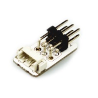
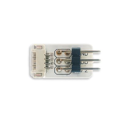
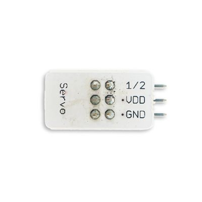
| − | + | ::<p style="color: #000000;font-size:120%">Sensor-Servo Connector是舵机转接板,用于连接舵机和扩展模块接口。</p> | |
| − | + | |} | |
| − | == | + | <br> |
| − | + | <br> | |
| − | | | + | <p style="color: #333333;font-size:155%">'''引脚'''</p> |
| − | | | + | {| border="0" cellpadding="10" width="90%" |
| − | | | + | |- |
| − | + | |width="35%" valign="center" align="left"| | |
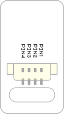
| − | + | *IN'''<big style="color: #00A0A6">(数字信号)</big>''' | |
| − | 舵机没法直接和扩展模块(Hub)连接,需要借助舵机转接板。舵机转接板上下各有3个插针,可以同时转接两个舵机。 | + | **PIN1:GND |
| + | **PIN2:VCC | ||
| + | **PIN3:IO1 | ||
| + | **PIN4:IO2 | ||
| + | |width="35%" valign="top" align="center"| | ||
| + | [[file: Sensor_backpin.png|130px|center]] | ||
| + | |width="25%" valign="top" align="center"| | ||
| + | |} | ||
| + | <br> | ||
| + | ---- | ||
| + | <br> | ||
| + | <p style="color: #333333;font-size:155%">'''接线说明'''</p> | ||
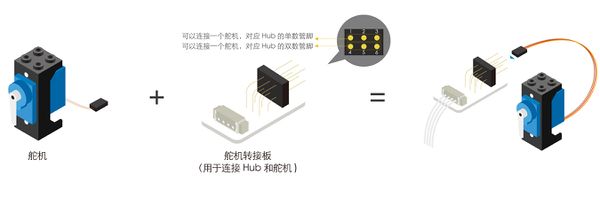
| + | *舵机没法直接和扩展模块(Hub)连接,需要借助舵机转接板。舵机转接板上下各有3个插针,可以同时转接两个舵机。 | ||
[[File:anywhere_Servo-Servo Connector.jpg|600px|center]] | [[File:anywhere_Servo-Servo Connector.jpg|600px|center]] | ||
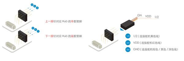
| − | 舵机和舵机转接板连接时注意“正反”,确保GND、VCC、1/2三根线连接正确。上一排针对应Hub的单数管脚,下一排针对应Hub的双数管脚。如舵机转接板接到Hub的6/ | + | *舵机和舵机转接板连接时注意“正反”,确保GND、VCC、1/2三根线连接正确。上一排针对应Hub的单数管脚,下一排针对应Hub的双数管脚。如舵机转接板接到Hub的6/7管脚,若舵机接在*下一排排针,则控制管脚为6,接上一排控制管脚为7。 |
[[File:anywhere_Servo-Servo Connector1.jpg|600px|center]] | [[File:anywhere_Servo-Servo Connector1.jpg|600px|center]] | ||
| − | + | <br> | |
| − | + | ---- | |
| − | + | <br> | |
| − | = | + | <p style="color: #333333;font-size:155%">'''示例教程'''</p> |
*[[舵机]]<br> | *[[舵机]]<br> | ||
*[[舵机使用]]<br> | *[[舵机使用]]<br> | ||
*[[红外控制舵机角度]]<br> | *[[红外控制舵机角度]]<br> | ||
| + | <br> | ||
| + | ---- | ||
| + | <br> | ||
| + | <p style="color: #333333;font-size:155%">'''Q&A'''</p> | ||
| + | <br> | ||
| + | ---- | ||
| + | <br> | ||
| + | <p style="color: #333333;font-size:155%">'''历史'''</p> | ||
| − | + | <br> | |
| − | + | ---- | |
| − | = | + | <br> |
| + | <p style="color: #333333;font-size:135%">'''图库'''</p> | ||
{| border="0" cellpadding="10" width="100%" | {| border="0" cellpadding="10" width="100%" | ||
|- | |- | ||
|width="50%" valign="top" align="left"| | |width="50%" valign="top" align="left"| | ||
| − | [[file:Sensor-Servo Connector-F.JPG|thumb|400px|center|Sensor- | + | [[file:Sensor-Servo Connector-F.JPG|thumb|400px|center|Sensor-PIR Front]] |
|width="50%" valign="top" align="left"| | |width="50%" valign="top" align="left"| | ||
| − | [[file: Sensor-Servo Connector-b.JPG|thumb|400px|center|Sensor- | + | [[file: Sensor-Servo Connector-b.JPG|thumb|400px|center|Sensor-PIR Back]] |
|} | |} | ||
|} | |} | ||
| + | |||
| + | |||
| + | |||
| + | |||
| + | |||
| + | [[MCookie_传感器系列|返回mCookie_传感器系列页面]] | ||
2017年12月13日 (三) 18:00的版本
| |
|
引脚
|
接线说明
- 舵机没法直接和扩展模块(Hub)连接,需要借助舵机转接板。舵机转接板上下各有3个插针,可以同时转接两个舵机。
- 舵机和舵机转接板连接时注意“正反”,确保GND、VCC、1/2三根线连接正确。上一排针对应Hub的单数管脚,下一排针对应Hub的双数管脚。如舵机转接板接到Hub的6/7管脚,若舵机接在*下一排排针,则控制管脚为6,接上一排控制管脚为7。
示例教程
Q&A
历史
图库
|}
