|
|
| (未显示2个用户的32个中间版本) |
| 第29行: |
第29行: |
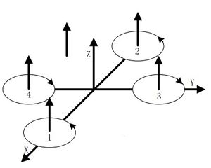
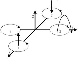
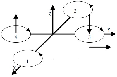
| | <br>为了在水平上获得一个推力,增加电机2的转速,尾部的推力增加;降低电机1的转速,头部的推力减小;整个机身会向前倾,合成了一个水平向前的推力,机身便能够向前运动。同时保持电机3和4的转速,反扭矩平衡,才能够保证机身平稳地向前。向后运动正好与向前运动相反。 | | <br>为了在水平上获得一个推力,增加电机2的转速,尾部的推力增加;降低电机1的转速,头部的推力减小;整个机身会向前倾,合成了一个水平向前的推力,机身便能够向前运动。同时保持电机3和4的转速,反扭矩平衡,才能够保证机身平稳地向前。向后运动正好与向前运动相反。 |
| | <br>因为四旋翼飞行器是中心对称的,前后运动和侧向运动的控制是完全类似的,两组正反电机的控制方式对调即可。例如,保持电机1和2的转速不变,增加电机4的转速而降低电机3的转速,便能够产生向左的水平力,于是机身向左运动。 | | <br>因为四旋翼飞行器是中心对称的,前后运动和侧向运动的控制是完全类似的,两组正反电机的控制方式对调即可。例如,保持电机1和2的转速不变,增加电机4的转速而降低电机3的转速,便能够产生向左的水平力,于是机身向左运动。 |
| − | <br>
| |
| − | <br>
| |
| − | {| style="width: 800px;" | colspan="2" |
| |
| − | |-
| |
| − | | style="width:300px" align="left"|
| |
| − | <br>
| |
| − | [[File:head-back-sport.jpg|enter|300px]]
| |
| | | | |
| − | | style="width:500px" align="left"| | + | [[File:head-back-sport.jpg|center|400px]] |
| − | <br>
| + | |
| − | [[File:right-left-sport.jpg|center|300px]] | + | |
| − | |-
| + | [[File:right-left-sport.jpg|center|400px]] |
| − | |
| |
| − | |}
| |
| − | <br>
| |
| − | <br>
| |
| | | | |
| | ====偏航运动==== | | ====偏航运动==== |
| 第57行: |
第46行: |
| | |- | | |- |
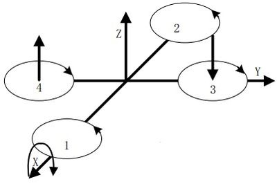
| | |同样是因为中心对称的缘故,滚转运动与俯仰运动的原理一样。维持电机1和2的转速不变,改变电机3和4的转速,产生不平衡的力矩,使得机身绕着X轴做出滚转的运动。 | | |同样是因为中心对称的缘故,滚转运动与俯仰运动的原理一样。维持电机1和2的转速不变,改变电机3和4的转速,产生不平衡的力矩,使得机身绕着X轴做出滚转的运动。 |
| − | {| style="width: 800px;" | colspan="2" |
| |
| − | |-
| |
| − | | style="width:300px" align="left"|
| |
| − | <br>
| |
| − | [[File:headback-sport.jpg|enter|300px]]
| |
| | | | |
| − | | style="width:500px" align="left"| | + | [[File:headback-sport.jpg|center|400px]] |
| − | <br>
| + | |
| − | [[File:turn over-sport.jpg|center|300px]] | + | |
| − | |-
| + | [[File:turn over-sport.jpg|center|400px]] |
| − | |
| |
| − | |}
| |
| − | <br>
| |
| − | <br>
| |
| | | | |
| | ===控制流程=== | | ===控制流程=== |
| 第96行: |
第76行: |
| | |模块||数量||功能 | | |模块||数量||功能 |
| | |- | | |- |
| − | |Microduino-CoreRF||1||核心板 | + | |[[Microduino-CoreRF/zh]]||1||核心板 |
| | |- | | |- |
| − | |Microduino-USBTTL ||1||下载程序 | + | |[[Microduino-USBTTL]] ||1||下载程序 |
| | |- | | |- |
| − | |Microduino-10DOF ||1||姿态稳定 | + | |[[Microduino-10DOF]] ||1||姿态稳定 |
| | |- | | |- |
| − | |Microduino-QuadCopter||1||加长无线传输距离 | + | |[[Microduino-QuadCopter]]||1||四轴驱动底板 |
| | |- | | |- |
| − | |2.4G天线||1||四轴驱动 | + | |[[2.4G天线]]||1||加长无线传输距离 |
| | |} | | |} |
| | | | |
| 第124行: |
第104行: |
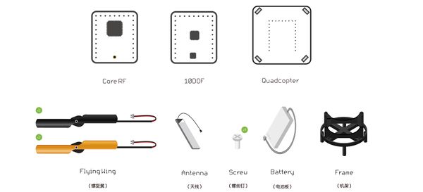
| | [[File:四轴物料1.jpg|center|600px]] | | [[File:四轴物料1.jpg|center|600px]] |
| | | | |
| − | [[File:四轴步骤.jpg|center|600px]] | + | *'''Step 1''':将四个螺旋翼按照如图所示方向插入到机架的对应机口上。 |
| − | | + | [[File:Quostep1.jpg|center|600px]] |
| − | *'''Step 1''':将Microduino-QuadCopter底板安置在机架底座上,并用螺丝将其固定住。 | + | *'''Step 2''':将电池放到机架底部的对应位置. |
| − | **飞行器头部方向默认是Upin口的开口方向,规定其为正前方。
| + | [[File:Quostep2.jpg|center|600px]] |
| − | **Microduino-QuadCopter底板上各边中间都有一个内凹的设计,将机架四个立柱卡在内凹处。
| + | *'''Step 3''':将模块底板放入机架顶部位置,再将旋翼的接线插入模块底板对应的接口位置。 |
| − | | + | [[File:Quostep3.jpg|center|600px]] |
| − | *'''Step 2''':将四个电机臂插进机架底座上. | + | *'''Step 4''':将天线接在CoreRF上,之后与10DOF上下叠加在一起,加在底板上,Upin方向朝两个橙色桨安装(如图所示)。 |
| − | **每个螺旋桨上都有字母标识”A”或”B”。
| + | [[File:Quostep4.jpg|center|600px]] |
| − | **定义橙色桨为正前方(与Microduino-QuadCopter的Upin口的开口方向一致)。
| + | *'''Step 5''':将底板模块的接线头和电池的连线进行连接。 |
| − | **橙色桨A左,B右;黑色桨B左A右。
| + | [[File:Quostep5.jpg|center|600px]] |
| − | | + | *'''Step 6''':将CoreRF上的天线贴纸撕下来贴在机架背后任意位置,至此无人机组合完成。 |
| − | *'''Step 3''':将机架反过来,可以看到4个螺丝孔,用螺丝将机架与电极臂固定住。 | + | [[File:Quostep6.jpg|center|600px]] |
| − | | |
| − | *'''Step 4''':在固定好四个机臂后将四个电机的导线接到飞行器控制板对应的接口上。底座接口和电池接口是匹配,带有防差错设计(插反会插不进去)。 | |
| − | | |
| − | *'''Step 5''':将电池卡进机架底座反面的电池槽里,并把电池线与机架底座电源线连在一起。 | |
| | **两根先正负极不要反了,红色线连红色线,黑色线连黑色线。 | | **两根先正负极不要反了,红色线连红色线,黑色线连黑色线。 |
| | **电池线从电极臂下方连接,防止螺旋桨转动时与电池线碰撞。 | | **电池线从电极臂下方连接,防止螺旋桨转动时与电池线碰撞。 |
| − |
| |
| − | 请参考文字说明与说明图片进行拼装
| |
| − |
| |
| | | | |
| | ===程序下载调试=== | | ===程序下载调试=== |
| | *确认你搭建了Microduino的开发环境,否则参考:[[Microduino Getting started/zh]] | | *确认你搭建了Microduino的开发环境,否则参考:[[Microduino Getting started/zh]] |
| − | *代码:[https://github.com/wasdpkj/MultiWii_for_Microduino/ MultiWii_for_Microduino] | + | *百度盘地址: |
| | + | **Joypad代码:http://pan.baidu.com/s/1o6zVh3O 提取码:z6k2 |
| | + | **飞行器代码:http://pan.baidu.com/s/1mgrRN7q 提取码:un3x |
| | + | |
| | + | *Github 地址 |
| | + | **Joypad代码:[https://github.com/wasdpkj/Joypad_RC/tree/master/Joypad_RC Joypad_RC] |
| | + | **飞行器代码: [https://github.com/Microduino/MultiWii_for_Microduino/tree/master/MultiWii_for_CoreRF] |
| | *将Microduino-CoreRF、Microduino-USBTTL叠堆到一起,并用MicroUSB数据线将Microduino-USBTTL和电脑连接起来。 | | *将Microduino-CoreRF、Microduino-USBTTL叠堆到一起,并用MicroUSB数据线将Microduino-USBTTL和电脑连接起来。 |
| | *打开Arduino IDE编程软件,点击 【文件】->【打开】,打开MultiWii_CoreRF中的【MultiWii_RF】程序,在菜单栏的Tools下的Board选择板卡Microduino-Core RF | | *打开Arduino IDE编程软件,点击 【文件】->【打开】,打开MultiWii_CoreRF中的【MultiWii_RF】程序,在菜单栏的Tools下的Board选择板卡Microduino-Core RF |
| 第217行: |
第196行: |
| | |TFT连接线||1||连接 | | |TFT连接线||1||连接 |
| | |} | | |} |
| − | [[File:Joypad0_Pitch_Roll0.jpg|center|600px]]
| + | |
| | *其他设备 | | *其他设备 |
| | {|class="wikitable" | | {|class="wikitable" |
| 第237行: |
第216行: |
| | |TFT连接线||1||连接 | | |TFT连接线||1||连接 |
| | |} | | |} |
| − | [[File:Joypad0_Pitch_Roll.jpg|center|600px]] | + | [[File:Joypad物料.jpg|center|600px]] |
| | ===Joypad搭建与调试=== | | ===Joypad搭建与调试=== |
| | ====Joypad搭建==== | | ====Joypad搭建==== |
| − | *'''Step 1''':给Joypad的Microduino-CorRF下载程序。
| + | 给Joypad的Microduino-CorRF下载程序。 |
| − | **打开MultiWii_CoreRF中的【Joypad_RC】程序,在编译结束后,选择好板卡和端口进行直接下载。 | + | *打开MultiWii_CoreRF中的【Joypad_RC】程序,在编译结束后,选择好板卡和端口进行直接下载 |
| − | [[File:Microduino-CoreRF_Pitch_Roll.jpg|center|600px]]
| |
| − | *'''Step 2''':将Microduino-TFT从Microduino-Joypad面板后面卡进Microduino-Joypad面板上,用尼龙螺丝固定,注意Microduino-TFT安装方向。
| |
| − | [[File:Microduino_Joypad_TFT1.jpg|center|400px]]
| |
| − | | |
| − | *'''Step 3''':先在图示位置安装尼龙柱并在Joypad反面用尼龙螺母固定尼龙柱(尼龙柱由两个小尼龙柱组合而成)。再把2.4G天线插在Microduino-CoreRF模块上,并把Microduino-CoreRF插入在Microduino-Joypad底板上的Upin27任意一个接口上。
| |
| − | [[File:Microduino_Joypad_nilong1.jpg|center|400px]]
| |
| − | | |
| − | *'''Step 4''':将Microduino-TFT与Microduino-Joypad通过转接线连接起来,接口有防差错设计,转接线插反就会插不进去
| |
| − | [[File:Microduino_Joypad_Connection1.jpg|center|400px]]
| |
| − | | |
| − | *'''Step 5''':将电池上面的开关拨到“Dry bat(1.5V)”的一边,电池(7号)装到电池盒里板上,注意正负极别装反了,电池盒标注了正负极;打开Joypad右边的开关观察是否供电,若无请用USB数据线接入左边的MicroUSB接口来激活系统。
| |
| − | |-
| |
| − | |也可以不用电池,直接通过USB线接入左边的MicroUSB来供电。
| |
| − | [[File:Joypad_Pitch_Roll1.png|center|400px]]
| |
| | | | |
| − | *'''Step 6''':用塑料螺丝将底板和面板固定;先将遥感帽安装在摇杆上,按钮帽安装在按钮键上,再盖上上板用尼龙螺丝固定。(若按键与上板的按键口不好连接,可先将按键插入按键口,再与底板按键连接)。 | + | *'''Step 1''':将Microduino-TFT从Microduino-Joypad面板后面卡进Microduino-Joypad面板上,用尼龙螺丝固定,注意Microduino-TFT安装方向 |
| − | [[File:Joypad_Pitch_Roll2.jpg|center|400px]] | + | [[File:Joypadstep1.jpg|center|600px]] |
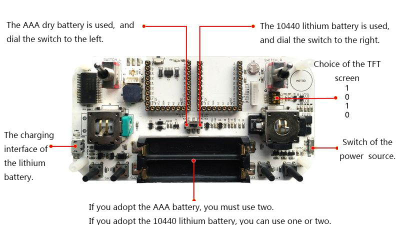
| − | | + | '''注意:接不同的电池需要拨动中间的开关,在图中已有标志。需要先拨开关再接入电池,否则会影响使用。''' |
| − | *'''Step 7''':你可以打开侧面电源开关,观察供电是否正常,是否正常进入系统。 | + | [[File:Joypadstep1_1.jpg|center|800px]] |
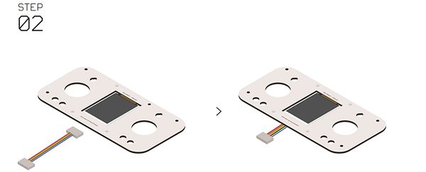
| − | [[File:Mic6roduAino_Joypad_switch.jpg||400px|center]] | + | *'''Step 2''':将传感器接线插在Microduino-TFT的接口上 |
| | + | [[File:Joypadstep2.jpg|center|600px]] |
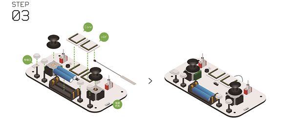
| | + | *'''Step 3''':首先分别将两个摇杆按键、电池、四个白色按键放入对应位置,之后将连接好天线的nRF模块和Core装到Joypad底板上 |
| | + | [[File:Joypadstep3.jpg|center|600px]] |
| | + | *'''Step 4''':将Microduino-TFT传感器接线的另一头接到底板上的相应位置,之后将长版螺丝帽放到四个角的相应位置 |
| | + | [[File:Joypadstep4.jpg|center|600px]] |
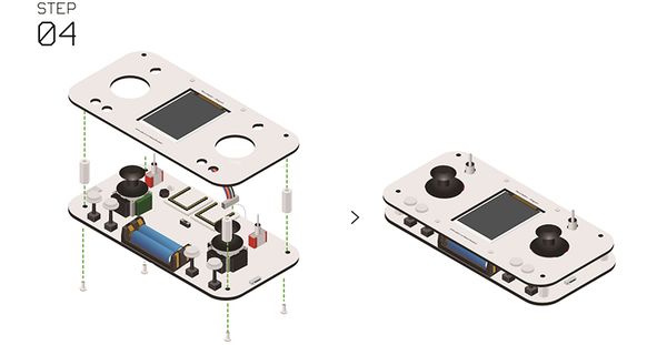
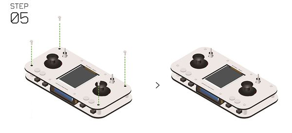
| | + | *'''Step 5''':将Joypad的表壳和底板使用螺丝和螺丝帽固定好 |
| | + | [[File:Joypadstep5.jpg|center|600px]] |
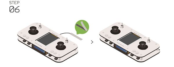
| | + | *'''Step 6''':组装完成后将天线上的贴纸撕下,将天线贴在底板背面的任意位置,至此Joypad组装完毕 |
| | + | [[File:Joypadstep6.jpg|center|600px]] |
| | | | |
| | ====Joypad搭建调试==== | | ====Joypad搭建调试==== |
| − | *遥控设置 | + | *按键对应 |
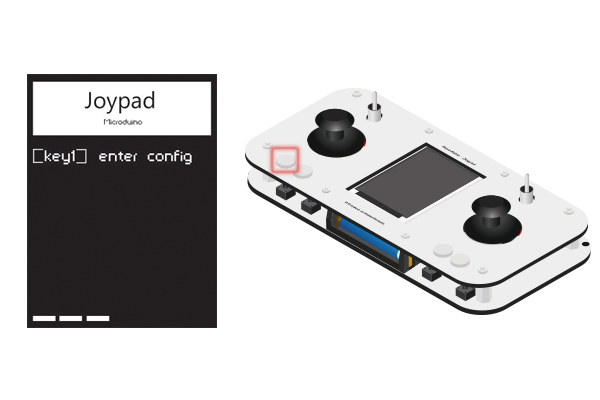
| − | **打开遥控器电源开关,看见屏幕有数据按下下图Key1键进入系统设置。 | + | 在打开Joypad之后的4秒左右时间之内按下Key1(下方最左侧的按键),会进入设置(Config)模式 |
| − | |- | + | [[File:Step1进入设置.jpg|600px|center|]] |
| − | |'''注意:必须在进入操作界面前进入(4S左右时间)。若未进入则重启进入'''
| + | *进入设置模式 |
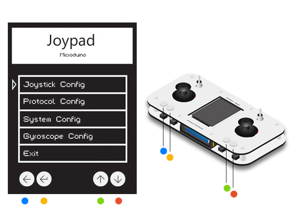
| | + | 按照图中的颜色,从左至右对应为Key1~Key4 |
| | + | [[File:Step1按键对应.jpg|600px|center|]] |
| | + | 注意:必须在进入操作界面前进入(4S左右时间)。若未进入则重启进入''' |
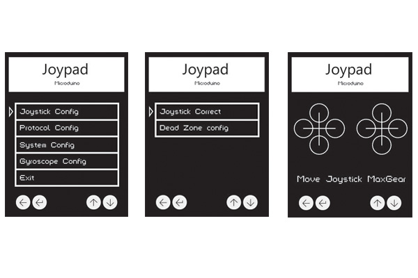
| | *摇杆校准 | | *摇杆校准 |
| − | **上下拨动左边摇杆,显示屏上第二个数据在0左右即可(下图黄色标记)。
| + | 按动Key3和Key4使光标上下移动,Key1为返回,Key2为确认 |
| | + | 选择第一项Joystick Config进入摇杆设置模式 |
| | + | 继续选择Joystick Correct进入摇杆校准模式。 |
| | + | 进入之后会显示如图中第三张图所示的界面,初始状态为两个十字 |
| | + | 此时摇动左右摇杆至最上,最下,最左,最右四个极限状态 |
| | + | (推荐操作方式:将摇杆摇动一圈) |
| | + | 摇动之后会看到十字的四个方向出现圆圈,圆圈扩大到最大状态证明已经是摇杆的极限位置 |
| | + | 校准之后按Key2确认并返回上一页面 |
| | + | [[File:Step2摇杆校准.jpg|600px|center|]] |
| | *选择控制模式 | | *选择控制模式 |
| − | **通过【key3】按键选择“Quad.” (四轴飞行器)(黑色表示选中)。
| + | 按Key1回到主界面,选择第二项Protocol Config进入模式选择 |
| − | **通过【key4】按键选择 “MPU OFF” (摇杆模式)。 | + | 选择第一项Mode,之后选择Quodro即四轴飞行器控制模式,按下Key2确认并返回 |
| − | **选择完按【key2】键完成配置。
| + | [[File:Step3设置四轴模式.jpg|600px|center|]] |
| − | [[File:Mic6roduAino_Joypad_over.jpg|400px|center|]] | + | *设置通信信道 |
| | + | 返回二级菜单,选择Quodrotor Channel按下Key2确认 |
| | + | 选择12,它是与MultiWii.h中"#define RF_Channel 12"中的设置相对应的 |
| | + | [[File:Step4通信通道设置.jpg|600px|center|]] |
| | 至此,飞行控制器和遥控器已经组装完成,接下来便是将两者结合起来,开始试飞,除了练习使用操纵杆,还要观察飞行器实际的飞行状态,以便进一步优化PID等参数。 | | 至此,飞行控制器和遥控器已经组装完成,接下来便是将两者结合起来,开始试飞,除了练习使用操纵杆,还要观察飞行器实际的飞行状态,以便进一步优化PID等参数。 |
| | | | |
| 第310行: |
第298行: |
| | 解锁后,中间摇杆往上推就可以加油门,四轴就可以飞起来,前后左右则通过重力感应来控制。 | | 解锁后,中间摇杆往上推就可以加油门,四轴就可以飞起来,前后左右则通过重力感应来控制。 |
| | [[File:Qua_app-ok.png|center|600px]] | | [[File:Qua_app-ok.png|center|600px]] |
| − | ==代码及注释==
| + | |
| | ==程序说明== | | ==程序说明== |
| − |
| |
| − | ==Joypad程序及说明==
| |
| − | Joypad_RC.ino
| |
| − | <source lang="cpp">
| |
| − | #include "Arduino.h"
| |
| − | #include "def.h"
| |
| − | #include "time.h"
| |
| − | #include "bat.h"
| |
| − | #if defined(__AVR_ATmega1284P__) || defined(__AVR_ATmega644P__) || defined(__AVR_ATmega128RFA1__)
| |
| − | #include "mpu.h"
| |
| − | #endif
| |
| − | #include "joy.h"
| |
| − | #include "key.h"
| |
| − | #include "data.h"
| |
| − | #include "nrf.h"
| |
| − | #include "mwc.h"
| |
| − | #include "tft.h"
| |
| − | #include "eep.h"
| |
| − |
| |
| − | #if defined(__AVR_ATmega128RFA1__)
| |
| − | #include <ZigduinoRadio.h>
| |
| − | #endif
| |
| − |
| |
| − | //joypad================================
| |
| − | #include <Joypad.h>
| |
| − | //eeprom================================
| |
| − | #include <EEPROM.h>
| |
| − | //TFT===================================
| |
| − | #include <Adafruit_GFX.h> // Core graphics library
| |
| − | #include <Adafruit_ST7735.h> // Hardware-specific
| |
| − | #include <SPI.h>
| |
| − | //rf====================================
| |
| − | #include <RF24Network.h>
| |
| − | #include <RF24.h>
| |
| − |
| |
| − | #if defined(__AVR_ATmega1284P__) || defined(__AVR_ATmega644P__) || defined(__AVR_ATmega128RFA1__)
| |
| − | //MPU===================================
| |
| − | #include "Wire.h"
| |
| − | #include "I2Cdev.h"
| |
| − | #include "MPU6050_6Axis_MotionApps20.h"
| |
| − | #endif
| |
| − |
| |
| − | //spi===================================
| |
| − | #include <SPI.h>
| |
| − |
| |
| − | void setup()
| |
| − | {
| |
| − | // initialize serial communication at 115200 bits per second:
| |
| − |
| |
| − | #ifdef Serial_DEBUG
| |
| − | Serial.begin(115200);
| |
| − | delay(100);
| |
| − | Serial.println("========hello========");
| |
| − | #endif
| |
| − |
| |
| − | //---------------
| |
| − | key_init();
| |
| − |
| |
| − | //---------------
| |
| − | #ifdef Serial_DEBUG
| |
| − | Serial.println("\n\r EEPROM READ...");
| |
| − | #endif
| |
| − | eeprom_read();
| |
| − |
| |
| − | //---------------
| |
| − | #ifdef Serial_DEBUG
| |
| − | Serial.println("\n\r TFT INIT...");
| |
| − | #endif
| |
| − | TFT_init(true, tft_rotation);
| |
| − |
| |
| − | //---------------
| |
| − | #ifdef Serial_DEBUG
| |
| − | Serial.println("\n\r TFT BEGIN...");
| |
| − | #endif
| |
| − | TIME1 = millis();
| |
| − | while (millis() - TIME1 < interval_TIME1)
| |
| − | {
| |
| − | TFT_begin();
| |
| − |
| |
| − | if (!Joypad.readButton(CH_SWITCH_1))
| |
| − | {
| |
| − | #ifdef Serial_DEBUG
| |
| − | Serial.println("\n\rCorrect IN...");
| |
| − | #endif
| |
| − |
| |
| − | //---------------
| |
| − | #ifdef Serial_DEBUG
| |
| − | Serial.println("\n\r TFT INIT...");
| |
| − | #endif
| |
| − | TFT_init(false, tft_rotation);
| |
| − |
| |
| − | while (1)
| |
| − | {
| |
| − | if (!TFT_config())
| |
| − | break;
| |
| − | }
| |
| − | #ifdef Serial_DEBUG
| |
| − | Serial.println("\n\rCorrect OUT...");
| |
| − | #endif
| |
| − |
| |
| − | //---------------
| |
| − | #ifdef Serial_DEBUG
| |
| − | Serial.println("\n\r EEPROM WRITE...");
| |
| − | #endif
| |
| − | eeprom_write();
| |
| − | }
| |
| − | }
| |
| − |
| |
| − | //---------------
| |
| − | #ifdef Serial_DEBUG
| |
| − | Serial.println("\n\r TFT CLEAR...");
| |
| − | #endif
| |
| − | TFT_clear();
| |
| − |
| |
| − | //---------------
| |
| − | #ifdef Serial_DEBUG
| |
| − | Serial.println("\n\r TFT READY...");
| |
| − | #endif
| |
| − | TFT_ready();
| |
| − |
| |
| − | //---------------.l
| |
| − | if (mode_protocol) //Robot
| |
| − | {
| |
| − | SPI.begin(); //初始化SPI总线
| |
| − | radio.begin();
| |
| − | network.begin(/*channel*/ nrf_channal, /*node address*/ this_node);
| |
| − | }
| |
| − | else //QuadCopter
| |
| − | {
| |
| − | unsigned long _channel;
| |
| − | #if !defined(__AVR_ATmega128RFA1__)
| |
| − | switch (mwc_channal)
| |
| − | {
| |
| − | case 0:
| |
| − | _channel = 9600;
| |
| − | break;
| |
| − | case 1:
| |
| − | _channel = 19200;
| |
| − | break;
| |
| − | case 2:
| |
| − | _channel = 38400;
| |
| − | break;
| |
| − | case 3:
| |
| − | _channel = 57600;
| |
| − | break;
| |
| − | case 4:
| |
| − | _channel = 115200;
| |
| − | break;
| |
| − | }
| |
| − | #else if
| |
| − | _channel = mwc_channal;
| |
| − | #endif
| |
| − | mwc_port.begin(_channel);
| |
| − | }
| |
| − |
| |
| − | //---------------
| |
| − | #ifdef Serial_DEBUG
| |
| − | Serial.println("===========start===========");
| |
| − | #endif
| |
| − |
| |
| − | #if defined(__AVR_ATmega1284P__) || defined(__AVR_ATmega644P__) || defined(__AVR_ATmega128RFA1__)
| |
| − | if (mode_mpu) initMPU(); //initialize device
| |
| − | #endif
| |
| − | }
| |
| − |
| |
| − | void loop()
| |
| − | {
| |
| − | // unsigned long time = millis();
| |
| − |
| |
| − | #if defined(__AVR_ATmega1284P__) || defined(__AVR_ATmega644P__) || defined(__AVR_ATmega128RFA1__)
| |
| − | //MPU--------------------------------
| |
| − | if (mode_mpu)
| |
| − | getMPU();
| |
| − | #endif
| |
| − |
| |
| − | //DATA_begin------------------------------
| |
| − | data_begin();
| |
| − |
| |
| − | //DATA_send-------------------------------
| |
| − | if (millis() < time2) time2 = millis();
| |
| − | if (millis() - time2 > interval_time2)
| |
| − | {
| |
| − | if (mode_protocol) nrf_send(); //Robot
| |
| − | else data_send(); //QuadCopter
| |
| − |
| |
| − | time2 = millis();
| |
| − | }
| |
| − |
| |
| − | //节点查错-------------------------------
| |
| − | vodebug();
| |
| − |
| |
| − | //BAT--------------------------------
| |
| − | if (time3 > millis()) time3 = millis();
| |
| − | if (millis() - time3 > interval_time3)
| |
| − | {
| |
| − | vobat();
| |
| − | time3 = millis();
| |
| − | }
| |
| − |
| |
| − | //TFT------------------------------------
| |
| − | TFT_run();
| |
| − |
| |
| − | //===================================
| |
| − | // time = millis() - time;
| |
| − |
| |
| − | // Serial.println(time, DEC); //loop time
| |
| − | }
| |
| − | </cpp>
| |
| − | BAT.h
| |
| − | <source lang="cpp">
| |
| − | int8_t _V_bat = _V_min;
| |
| − |
| |
| − | boolean mcu_voltage = true; // 5.0 or 3.3
| |
| − | #define _V_fix 0.2 //fix battery voltage
| |
| − | #define _V_math(Y) (_V_fix+((Y*analogRead(PIN_bat)/1023.0f)/(33.0f/(51.0f+33.0f))))
| |
| − |
| |
| − | void vobat()
| |
| − | {
| |
| − | //_V_bat=10*((voltage*analogRead(PIN_bat)/1023.0f)/(33.0f/(51.0f+33.0f)));
| |
| − | _V_bat = _V_math(mcu_voltage ? 50 : 33);
| |
| − | _V_bat = constrain(_V_bat, _V_min, _V_max);
| |
| − |
| |
| − | #ifdef Serial_DEBUG
| |
| − | Serial.print("_V_bat: ");
| |
| − | Serial.println(_V_bat);
| |
| − | #endif
| |
| − | }
| |
| − | </source>
| |
| − | data.h
| |
| − | <source lang="cpp">
| |
| − | #include "Arduino.h"
| |
| − |
| |
| − | byte inBuf[16];
| |
| − |
| |
| − | int16_t outBuf[8] =
| |
| − | {
| |
| − | Joy_MID, Joy_MID, Joy_MID, Joy_MID, Joy_MID, Joy_MID, Joy_MID, Joy_MID
| |
| − | };
| |
| − |
| |
| − | boolean AUX[4] = {0, 0, 0, 0};
| |
| − | //======================================
| |
| − | void data_begin()
| |
| − | {
| |
| − | Joy();
| |
| − |
| |
| − | if (mode_protocol) //Robot
| |
| − | {
| |
| − | if (!sw_l)
| |
| − | {
| |
| − | Joy_x = Joy_MID;
| |
| − | Joy_y = Joy_MID;
| |
| − | Joy1_x = Joy_MID;
| |
| − | Joy1_y = Joy_MID;
| |
| − | }
| |
| − | }
| |
| − | else //QuadCopter
| |
| − | {
| |
| − | if (!sw_l)
| |
| − | Joy_y = Joy_MID - Joy_maximum;
| |
| − | }
| |
| − |
| |
| − | //but---------------------------------
| |
| − | for (uint8_t a = 0; a < 4; a++)
| |
| − | {
| |
| − | if (key_get(a, 1)) AUX[a] = !AUX[a];
| |
| − | }
| |
| − |
| |
| − | outBuf[0] = Joy1_x;
| |
| − | outBuf[1] = Joy1_y;
| |
| − | outBuf[2] = Joy_x;
| |
| − | outBuf[3] = Joy_y;
| |
| − | outBuf[4] = map(AUX[0], 0, 1, Joy_MID - Joy_maximum, Joy_MID + Joy_maximum);
| |
| − | outBuf[5] = map(AUX[1], 0, 1, Joy_MID - Joy_maximum, Joy_MID + Joy_maximum);
| |
| − | outBuf[6] = map(AUX[2], 0, 1, Joy_MID - Joy_maximum, Joy_MID + Joy_maximum);
| |
| − | outBuf[7] = map(AUX[3], 0, 1, Joy_MID - Joy_maximum, Joy_MID + Joy_maximum);
| |
| − | }
| |
| − |
| |
| − | </source>
| |
| − | def.h
| |
| − | <source lang="cpp">
| |
| − | #include "Arduino.h"
| |
| − |
| |
| − | //DEBUG-----------
| |
| − | #define Serial_DEBUG
| |
| − |
| |
| − | //MWC-------------
| |
| − | uint8_t mwc_channal = 11; //RF channel
| |
| − |
| |
| − | #if defined(__AVR_ATmega32U4__)
| |
| − | #define mwc_port Serial1 //Serial1 is D0 D1
| |
| − | #elif defined(__AVR_ATmega128RFA1__)
| |
| − | #define mwc_port ZigduinoRadio //RF
| |
| − | #else
| |
| − | #define mwc_port Serial //Serial is D0 D1
| |
| − | #endif
| |
| − |
| |
| − | //nRF-------------
| |
| − | #define interval_debug 2000 //节点查错间隔
| |
| − | uint8_t nrf_channal = 70; //0~125
| |
| − |
| |
| − | //Battery---------
| |
| − | #define PIN_bat A7 //BAT
| |
| − |
| |
| − | #define _V_max 41 //锂电池满电电压4.2V
| |
| − | #define _V_min 36 //锂电池没电电压3.7V
| |
| − |
| |
| − | #if defined(__AVR_ATmega1284P__) || defined(__AVR_ATmega644P__) || defined(__AVR_ATmega128RFA1__)
| |
| − | //MPU-------------
| |
| − | #define MPU_maximum 70
| |
| − | #endif
| |
| − |
| |
| − |
| |
| − | //Time------------
| |
| − | #define interval_TIME1 2000 //setup delay
| |
| − | #define interval_time2 40 //send interval
| |
| − | #define interval_time3 1000 //battery interval
| |
| − | </source>
| |
| − | eep.h
| |
| − | <source lang="cpp">
| |
| − | #include "Arduino.h"
| |
| − |
| |
| − | #include <EEPROM.h>
| |
| − |
| |
| − | #define EEPROM_write(address, p) {int i = 0; byte *pp = (byte*)&(p);for(; i < sizeof(p); i++) EEPROM.write(address+i, pp[i]);}
| |
| − | #define EEPROM_read(address, p) {int i = 0; byte *pp = (byte*)&(p);for(; i < sizeof(p); i++) pp[i]=EEPROM.read(address+i);}
| |
| − |
| |
| − | struct config_type
| |
| − | {
| |
| − | int16_t eeprom_correct_min[4];
| |
| − | int16_t eeprom_correct_max[4];
| |
| − | uint8_t eeprom_Joy_deadzone_val;
| |
| − | #if defined(__AVR_ATmega1284P__) || defined(__AVR_ATmega644P__) || defined(__AVR_ATmega128RFA1__)
| |
| − | boolean eeprom_mode_mpu;
| |
| − | #endif
| |
| − | boolean eeprom_mode_protocol;
| |
| − | uint8_t eeprom_mwc_channal;
| |
| − | uint8_t eeprom_nrf_channal;
| |
| − | boolean eeprom_tft_theme;
| |
| − | boolean eeprom_tft_rotation;
| |
| − | boolean eeprom_mcu_voltage;
| |
| − | };
| |
| − |
| |
| − | //======================================
| |
| − | void eeprom_read()
| |
| − | {
| |
| − | //EEPROM读取赋值
| |
| − | config_type config_readback;
| |
| − | EEPROM_read(0, config_readback);
| |
| − |
| |
| − | for (uint8_t a = 0; a < 4; a++)
| |
| − | {
| |
| − | joy_correct_min[a] = config_readback.eeprom_correct_min[a];
| |
| − | joy_correct_max[a] = config_readback.eeprom_correct_max[a];
| |
| − | }
| |
| − | Joy_deadzone_val = config_readback.eeprom_Joy_deadzone_val;
| |
| − |
| |
| − | mode_protocol = config_readback.eeprom_mode_protocol;
| |
| − | #if defined(__AVR_ATmega1284P__) || defined(__AVR_ATmega644P__) || defined(__AVR_ATmega128RFA1__)
| |
| − | mode_mpu = config_readback.eeprom_mode_mpu;
| |
| − | #endif
| |
| − |
| |
| − | mwc_channal = config_readback.eeprom_mwc_channal;
| |
| − | nrf_channal = config_readback.eeprom_nrf_channal;
| |
| − | tft_theme = config_readback.eeprom_tft_theme;
| |
| − | tft_rotation = config_readback.eeprom_tft_rotation;
| |
| − | mcu_voltage = config_readback.eeprom_mcu_voltage;
| |
| − | }
| |
| − |
| |
| − | void eeprom_write()
| |
| − | {
| |
| − | // 定义结构变量config,并定义config的内容
| |
| − | config_type config;
| |
| − |
| |
| − | for (uint8_t a = 0; a < 4; a++)
| |
| − | {
| |
| − | config.eeprom_correct_min[a] = joy_correct_min[a];
| |
| − | config.eeprom_correct_max[a] = joy_correct_max[a];
| |
| − | }
| |
| − | config.eeprom_Joy_deadzone_val = Joy_deadzone_val;
| |
| − |
| |
| − | config.eeprom_mode_protocol = mode_protocol;
| |
| − | #if defined(__AVR_ATmega1284P__) || defined(__AVR_ATmega644P__) || defined(__AVR_ATmega128RFA1__)
| |
| − | config.eeprom_mode_mpu = mode_mpu;
| |
| − | #endif
| |
| − |
| |
| − | config.eeprom_mwc_channal = mwc_channal;
| |
| − | config.eeprom_nrf_channal = nrf_channal;
| |
| − | config.eeprom_tft_theme = tft_theme;
| |
| − | config.eeprom_tft_rotation = tft_rotation;
| |
| − | config.eeprom_mcu_voltage = mcu_voltage;
| |
| − |
| |
| − | // 变量config存储到EEPROM,地址0写入
| |
| − | EEPROM_write(0, config);
| |
| − | }
| |
| − | </source>
| |
| − | joy.h
| |
| − | <source lang="cpp">
| |
| − | #include "Arduino.h"
| |
| − |
| |
| − | #include <Joypad.h>
| |
| − |
| |
| − | //Joy-------------
| |
| − | //1000~2000
| |
| − | uint8_t Joy_deadzone_val = 10;
| |
| − | #define Joy_s_maximum 200 //MAX 300
| |
| − | #define Joy_maximum 450 //MAX 500
| |
| − | #define Joy_MID 1500 //1500
| |
| − |
| |
| − | boolean mode_mpu, mode_protocol; //{(0: 0 is mwc, 1 is nrf),(1: 0 is mpu, 1 is no mpu)}
| |
| − |
| |
| − | int16_t joy_correct_max[4], joy_correct_min[4];
| |
| − | int16_t Joy_x, Joy_y, Joy1_x, Joy1_y;
| |
| − |
| |
| − | int16_t s_lig, s_mic;
| |
| − |
| |
| − | boolean Joy_sw, Joy1_sw;
| |
| − |
| |
| − | boolean but1, but2, but3, but4;
| |
| − |
| |
| − | boolean sw_l, sw_r;
| |
| − |
| |
| − | //======================================
| |
| − | int16_t Joy_dead_zone(int16_t _Joy_vol)
| |
| − | {
| |
| − | if (abs(_Joy_vol) > Joy_deadzone_val)
| |
| − | return ((_Joy_vol > 0) ? (_Joy_vol - Joy_deadzone_val) : (_Joy_vol + Joy_deadzone_val));
| |
| − | else
| |
| − | return 0;
| |
| − | }
| |
| − |
| |
| − | int16_t Joy_i(int16_t _Joy_i, boolean _Joy_b, int16_t _Joy_MIN, int16_t _Joy_MAX)
| |
| − | {
| |
| − | int16_t _Joy_a;
| |
| − | switch (_Joy_i)
| |
| − | {
| |
| − | case 0:
| |
| − | _Joy_a = Joy_dead_zone(Joypad.readJoystickX());
| |
| − | break;
| |
| − | case 1:
| |
| − | _Joy_a = Joypad.readJoystickY(); //throt
| |
| − | break;
| |
| − | case 2:
| |
| − | _Joy_a = Joy_dead_zone(Joypad.readJoystick1X());
| |
| − | break;
| |
| − | case 3:
| |
| − | _Joy_a = Joy_dead_zone(Joypad.readJoystick1Y());
| |
| − | break;
| |
| − | }
| |
| − |
| |
| − | if (_Joy_b)
| |
| − | {
| |
| − | if (_Joy_a < 0)
| |
| − | _Joy_a = map(_Joy_a, joy_correct_min[_Joy_i], 0, _Joy_MAX, Joy_MID);
| |
| − | else
| |
| − | _Joy_a = map(_Joy_a, 0, joy_correct_max[_Joy_i], Joy_MID, _Joy_MIN);
| |
| − |
| |
| − | if (_Joy_a < _Joy_MIN) _Joy_a = _Joy_MIN;
| |
| − | if (_Joy_a > _Joy_MAX) _Joy_a = _Joy_MAX;
| |
| − | }
| |
| − | return _Joy_a;
| |
| − | }
| |
| − |
| |
| − | void Joy()
| |
| − | {
| |
| − | sw_l = Joypad.readButton(CH_SWITCH_L);
| |
| − | sw_r = Joypad.readButton(CH_SWITCH_R);
| |
| − |
| |
| − | //------------------------------------
| |
| − | //s_lig=Joypad.readLightSensor();
| |
| − | //s_mic=Joypad.readMicrophone();
| |
| − |
| |
| − | //------------------------------------
| |
| − | Joy_sw = Joypad.readButton(CH_JOYSTICK_SW);
| |
| − | Joy1_sw = Joypad.readButton(CH_JOYSTICK1_SW);
| |
| − |
| |
| − | //------------------------------------
| |
| − | but1 = Joypad.readButton(CH_SWITCH_1);
| |
| − | but2 = Joypad.readButton(CH_SWITCH_2);
| |
| − | but3 = Joypad.readButton(CH_SWITCH_3);
| |
| − | but4 = Joypad.readButton(CH_SWITCH_4);
| |
| − |
| |
| − | #if defined(__AVR_ATmega1284P__) || defined(__AVR_ATmega644P__) || defined(__AVR_ATmega128RFA1__)
| |
| − | //====================================
| |
| − | int16_t y[3]; //MPU---------------------------------
| |
| − | if (mode_mpu) //MPU---------------------------------
| |
| − | {
| |
| − | for (uint8_t a = 0; a < 3; a++)
| |
| − | {
| |
| − | y[a] = ypr[a] * 180 / M_PI;
| |
| − | if (y[a] > MPU_maximum) y[a] = MPU_maximum;
| |
| − | if (y[a] < -MPU_maximum) y[a] = -MPU_maximum;
| |
| − | }
| |
| − | }
| |
| − | #endif
| |
| − |
| |
| − | if (Joypad.readButton(CH_SWITCH_R))
| |
| − | {
| |
| − | Joy_x = Joy_i(0, true, Joy_MID - Joy_maximum, Joy_MID + Joy_maximum);
| |
| − | Joy_y = Joy_i(1, true, Joy_MID - Joy_maximum, Joy_MID + Joy_maximum);
| |
| − |
| |
| − | #if defined(__AVR_ATmega1284P__) || defined(__AVR_ATmega644P__) || defined(__AVR_ATmega128RFA1__)
| |
| − | if (mode_mpu) //MPU---------------------------------
| |
| − | {
| |
| − | Joy1_x = map(y[2], -MPU_maximum, MPU_maximum, Joy_MID - Joy_maximum, Joy_MID + Joy_maximum);
| |
| − | Joy1_y = map(y[1], -MPU_maximum, MPU_maximum, Joy_MID - Joy_maximum, Joy_MID + Joy_maximum);
| |
| − | }
| |
| − | else
| |
| − | #endif
| |
| − | {
| |
| − | Joy1_x = Joy_i(2, true, Joy_MID - Joy_maximum, Joy_MID + Joy_maximum);
| |
| − | Joy1_y = Joy_i(3, true, Joy_MID - Joy_maximum, Joy_MID + Joy_maximum);
| |
| − | }
| |
| − | }
| |
| − | else
| |
| − | {
| |
| − | Joy_x = Joy_i(0, true, Joy_MID - Joy_s_maximum, Joy_MID + Joy_s_maximum);
| |
| − | Joy_y = Joy_i(1, true, mode_protocol ? Joy_MID - Joy_s_maximum : Joy_MID - Joy_maximum, mode_protocol ? Joy_MID + Joy_s_maximum : Joy_MID + Joy_maximum); // Robot,QuadCopter
| |
| − |
| |
| − | #if defined(__AVR_ATmega1284P__) || defined(__AVR_ATmega644P__) || defined(__AVR_ATmega128RFA1__)
| |
| − | if (mode_mpu) //MPU---------------------------------
| |
| − | {
| |
| − | Joy1_x = map(y[2], -MPU_maximum, MPU_maximum, Joy_MID - Joy_s_maximum, Joy_MID + Joy_s_maximum);
| |
| − | Joy1_y = map(y[1], -MPU_maximum, MPU_maximum, Joy_MID - Joy_s_maximum, Joy_MID + Joy_s_maximum);
| |
| − | }
| |
| − | else
| |
| − | #endif
| |
| − | {
| |
| − | Joy1_x = Joy_i(2, true, Joy_MID - Joy_s_maximum, Joy_MID + Joy_s_maximum);
| |
| − | Joy1_y = Joy_i(3, true, Joy_MID - Joy_s_maximum, Joy_MID + Joy_s_maximum);
| |
| − | }
| |
| − | }
| |
| − | }
| |
| − |
| |
| − | </source>
| |
| − | key.h
| |
| − | <source lang="cpp">
| |
| − | #include "arduino.h"
| |
| − |
| |
| − | uint8_t key_pin[4] = {CH_SWITCH_1, CH_SWITCH_2, CH_SWITCH_3, CH_SWITCH_4}; //按键1 2 3 4
| |
| − |
| |
| − | boolean key_status[4]; //按键
| |
| − | boolean key_cache[4]; //检测按键松开缓存
| |
| − |
| |
| − | void key_init()
| |
| − | {
| |
| − | for (uint8_t a = 0; a < 4; a++)
| |
| − | {
| |
| − | key_status[a] = LOW;
| |
| − | key_cache[a] = HIGH;
| |
| − | }
| |
| − | }
| |
| − |
| |
| − | boolean key_get(uint8_t _key_num, boolean _key_type)
| |
| − | {
| |
| − | key_cache[_key_num] = key_status[_key_num]; //缓存作判断用
| |
| − |
| |
| − | key_status[_key_num] = !Joypad.readButton(key_pin[_key_num]); //触发时
| |
| − |
| |
| − | switch (_key_type)
| |
| − | {
| |
| − | case 0:
| |
| − | if (!key_status[_key_num] && key_cache[_key_num]) //按下松开后
| |
| − | return true;
| |
| − | else
| |
| − | return false;
| |
| − | break;
| |
| − | case 1:
| |
| − | if (key_status[_key_num] && !key_cache[_key_num]) //按下松开后
| |
| − | return true;
| |
| − | else
| |
| − | return false;
| |
| − | break;
| |
| − | }
| |
| − | }
| |
| − | </source>
| |
| − | mpu.h
| |
| − | <source lang="cpp">
| |
| − | #if defined(__AVR_ATmega1284P__) || defined(__AVR_ATmega644P__) || defined(__AVR_ATmega128RFA1__)
| |
| − | #include "Wire.h"
| |
| − | #include "I2Cdev.h"
| |
| − | #include "MPU6050_6Axis_MotionApps20.h"
| |
| − |
| |
| − | MPU6050 mpu;
| |
| − |
| |
| − | //MPU-------------
| |
| − | #define MPU_maximum 70
| |
| − |
| |
| − | // MPU control/status vars
| |
| − | boolean dmpReady = false; // set true if DMP init was successful
| |
| − | uint8_t mpuIntStatus; // holds actual interrupt status byte from MPU
| |
| − | uint8_t devStatus; // return status after each device operation (0 = success, !0 = error)
| |
| − | uint16_t packetSize; // expected DMP packet size (default is 42 bytes)
| |
| − | uint16_t fifoCount; // count of all bytes currently in FIFO
| |
| − | uint8_t fifoBuffer[64]; // FIFO storage buffer
| |
| − |
| |
| − | // orientation/motion vars
| |
| − | Quaternion q; // [w, x, y, z] quaternion container
| |
| − | VectorInt16 aa; // [x, y, z] accel sensor measurements
| |
| − | VectorFloat gravity; // [x, y, z] gravity vector
| |
| − | float ypr[3]; // [yaw, pitch, roll] yaw/pitch/roll container and gravity vector
| |
| − |
| |
| − | void initMPU()
| |
| − | {
| |
| − | Wire.begin();
| |
| − | #ifdef Serial_DEBUG
| |
| − | Serial.println(F("Initializing I2C devices..."));
| |
| − | #endif
| |
| − | mpu.initialize();
| |
| − | // verify connection
| |
| − | #ifdef Serial_DEBUG
| |
| − | Serial.println(F("Testing device connections..."));
| |
| − | #endif
| |
| − | if (mpu.testConnection())
| |
| − | {
| |
| − | #ifdef Serial_DEBUG
| |
| − | Serial.println("MPU6050 connection successful");
| |
| − | #endif
| |
| − | }
| |
| − | #ifdef Serial_DEBUG
| |
| − | else
| |
| − | Serial.println(F("MPU6050 connection failed"));
| |
| − | #endif
| |
| − |
| |
| − | // load and configure the DMP
| |
| − | #ifdef Serial_DEBUG
| |
| − | Serial.println(F("Initializing DMP..."));
| |
| − | #endif
| |
| − | devStatus = mpu.dmpInitialize();
| |
| − |
| |
| − | // make sure it worked (returns 0 if so)
| |
| − | if (devStatus == 0) {
| |
| − | // turn on the DMP, now that it's ready
| |
| − | #ifdef Serial_DEBUG
| |
| − | Serial.println(F("Enabling DMP..."));
| |
| − | #endif
| |
| − | mpu.setDMPEnabled(true);
| |
| − |
| |
| − | mpuIntStatus = mpu.getIntStatus();
| |
| − |
| |
| − | // set our DMP Ready flag so the main loop() function knows it's okay to use it
| |
| − | // Serial.println(F("DMP ready! Waiting for first interrupt..."));
| |
| − | dmpReady = true;
| |
| − |
| |
| − | // get expected DMP packet size for later comparison
| |
| − | packetSize = mpu.dmpGetFIFOPacketSize();
| |
| − | }
| |
| − | else {
| |
| − | // ERROR!
| |
| − | // 1 = initial memory load failed
| |
| − | // 2 = DMP configuration updates failed
| |
| − | // (if it's going to break, usually the code will be 1)
| |
| − | #ifdef Serial_DEBUG
| |
| − | Serial.print(F("DMP Initialization failed (code "));
| |
| − | Serial.print(devStatus);
| |
| − | Serial.println(F(")"));
| |
| − | #endif
| |
| − | }
| |
| − | }
| |
| − |
| |
| − | void getMPU()
| |
| − | {
| |
| − | if (!dmpReady) return;
| |
| − | {
| |
| − | // reset interrupt flag and get INT_STATUS byte
| |
| − | mpuIntStatus = mpu.getIntStatus();
| |
| − |
| |
| − | // get current FIFO count
| |
| − | fifoCount = mpu.getFIFOCount();
| |
| − |
| |
| − | // check for overflow (this should never happen unless our code is too inefficient)
| |
| − | if ((mpuIntStatus & 0x10) || fifoCount == 1024)
| |
| − | {
| |
| − | // reset so we can continue cleanly
| |
| − | mpu.resetFIFO();
| |
| − | #ifdef Serial_DEBUG
| |
| − | Serial.println(F("FIFO overflow!"));
| |
| − | #endif
| |
| − | // otherwise, check for DMP data ready interrupt (this should happen frequently)
| |
| − | }
| |
| − | else if (mpuIntStatus & 0x02)
| |
| − | {
| |
| − | // wait for correct available data length, should be a VERY short wait
| |
| − | while (fifoCount < packetSize) fifoCount = mpu.getFIFOCount();
| |
| − |
| |
| − | // read a packet from FIFO
| |
| − | mpu.getFIFOBytes(fifoBuffer, packetSize);
| |
| − |
| |
| − | // track FIFO count here in case there is > 1 packet available
| |
| − | // (this lets us immediately read more without waiting for an interrupt)
| |
| − | fifoCount -= packetSize;
| |
| − |
| |
| − | // display ypr angles in degrees
| |
| − | mpu.dmpGetQuaternion(&q, fifoBuffer);
| |
| − | mpu.dmpGetGravity(&gravity, &q);
| |
| − | mpu.dmpGetYawPitchRoll(ypr, &q, &gravity);
| |
| − |
| |
| − | //Serial.print("ypr\t");
| |
| − | //Serial.print(ypr[0] * 180/M_PI);
| |
| − | //Serial.print("\t");
| |
| − | //Serial.print(ypr[1] * 180/M_PI);
| |
| − | //Serial.print("\t");
| |
| − | // Serial.println(ypr[2] * 180/M_PI);
| |
| − | }
| |
| − | }
| |
| − | }
| |
| − |
| |
| − | #endif
| |
| − | </source>
| |
| − | mwc.h
| |
| − | <source lang="cpp">
| |
| − | #include "Arduino.h"
| |
| − |
| |
| − | #if defined(__AVR_ATmega128RFA1__)
| |
| − | #include <ZigduinoRadio.h>
| |
| − | #endif
| |
| − |
| |
| − | int16_t RCin[8], RCoutA[8], RCoutB[8];
| |
| − |
| |
| − | int16_t p;
| |
| − | uint16_t read16()
| |
| − | {
| |
| − | uint16_t r = (inBuf[p++] & 0xFF);
| |
| − | r += (inBuf[p++] & 0xFF) << 8;
| |
| − | return r;
| |
| − | }
| |
| − |
| |
| − | uint16_t t, t1, t2;
| |
| − | uint16_t write16(boolean a)
| |
| − | {
| |
| − | if (a)
| |
| − | {
| |
| − | t1 = outBuf[p++] >> 8;
| |
| − | t2 = outBuf[p - 1] - (t1 << 8);
| |
| − | t = t1;
| |
| − | }
| |
| − | else
| |
| − | t = t2;
| |
| − | return t;
| |
| − | }
| |
| − |
| |
| − | typedef unsigned char byte;
| |
| − | byte getChecksum(byte length, byte cmd, byte mydata[])
| |
| − | {
| |
| − | //三个参数分别为: 数据长度 , 指令代码 , 实际数据数组
| |
| − | byte checksum = 0;
| |
| − | checksum ^= (length & 0xFF);
| |
| − | checksum ^= (cmd & 0xFF);
| |
| − | for (uint8_t i = 0; i < length; i++)
| |
| − | {
| |
| − | checksum ^= (mydata[i] & 0xFF);
| |
| − | }
| |
| − | return checksum;
| |
| − | }
| |
| − |
| |
| − | void data_rx()
| |
| − | {
| |
| − | // s_struct_w((int*)&inBuf,16);
| |
| − | p = 0;
| |
| − | for (uint8_t i = 0; i < 8; i++)
| |
| − | {
| |
| − | RCin[i] = read16();
| |
| − | /*
| |
| − | Serial.print("RC[");
| |
| − | Serial.print(i+1);
| |
| − | Serial.print("]:");
| |
| − |
| |
| − | Serial.print(inBuf[2*i],DEC);
| |
| − | Serial.print(",");
| |
| − | Serial.print(inBuf[2*i+1],DEC);
| |
| − |
| |
| − | Serial.print("---");
| |
| − | Serial.println(RCin[i]);
| |
| − | */
| |
| − | // delay(50); // delay in between reads for stability
| |
| − | }
| |
| − | }
| |
| − |
| |
| − | void data_tx()
| |
| − | {
| |
| − | p = 0;
| |
| − | for (uint8_t i = 0; i < 8; i++)
| |
| − | {
| |
| − | RCoutA[i] = write16(1);
| |
| − | RCoutB[i] = write16(0);
| |
| − |
| |
| − | /*
| |
| − | Serial.print("RC[");
| |
| − | Serial.print(i+1);
| |
| − | Serial.print("]:");
| |
| − |
| |
| − | Serial.print(RCout[i]);
| |
| − |
| |
| − | Serial.print("---");
| |
| − |
| |
| − | Serial.print(RCoutA[i],DEC);
| |
| − | Serial.print(",");
| |
| − | Serial.print(RCoutB[i],DEC);
| |
| − |
| |
| − | Serial.println("");
| |
| − | */
| |
| − | // delay(50); // delay in between reads for stability
| |
| − | }
| |
| − | }
| |
| − |
| |
| − | /*
| |
| − | if Core RF
| |
| − | [head,2byte,0xAA 0xBB] [type,1byte,0xCC] [data,16byte] [body,1byte(from getChecksum())]
| |
| − | Example:
| |
| − | AA BB CC 1A 01 1A 01 1A 01 2A 01 3A 01 4A 01 5A 01 6A 01 0D **
| |
| − | */
| |
| − | void data_send()
| |
| − | {
| |
| − | data_tx();
| |
| − |
| |
| − | #if !defined(__AVR_ATmega128RFA1__)
| |
| − | static byte buf_head[3];
| |
| − | buf_head[0] = 0x24;
| |
| − | buf_head[1] = 0x4D;
| |
| − | buf_head[2] = 0x3C;
| |
| − | #endif
| |
| − |
| |
| − | #define buf_length 0x10 //16
| |
| − | #define buf_code 0xC8 //200
| |
| − |
| |
| − | static byte buf_data[buf_length];
| |
| − | for (uint8_t a = 0; a < (buf_length / 2); a++)
| |
| − | {
| |
| − | buf_data[2 * a] = RCoutB[a];
| |
| − | buf_data[2 * a + 1] = RCoutA[a];
| |
| − | }
| |
| − |
| |
| − | static byte buf_body;
| |
| − | buf_body = getChecksum(buf_length, buf_code, buf_data);
| |
| − |
| |
| − | //----------------------
| |
| − | #if defined(__AVR_ATmega128RFA1__)
| |
| − | mwc_port.beginTransmission();
| |
| − | mwc_port.write(0xaa);
| |
| − | mwc_port.write(0xbb);
| |
| − | mwc_port.write(0xcc);
| |
| − | #else
| |
| − | for (uint8_t a = 0; a < 3; a++) {
| |
| − | mwc_port.write(buf_head[a]);
| |
| − | }
| |
| − | mwc_port.write(buf_length);
| |
| − | mwc_port.write(buf_code);
| |
| − | #endif
| |
| − | for (uint8_t a = 0; a < buf_length; a++) {
| |
| − | mwc_port.write(buf_data[a]);
| |
| − | }
| |
| − | mwc_port.write(buf_body);
| |
| − | #if defined(__AVR_ATmega128RFA1__)
| |
| − | mwc_port.endTransmission();
| |
| − | #endif
| |
| − | }
| |
| − | </source>
| |
| − | nrf.h
| |
| − | <source lang="cpp">
| |
| − | #include "Arduino.h"
| |
| − |
| |
| − | #include <RF24Network.h>
| |
| − | #include <RF24.h>
| |
| − | #include <SPI.h>
| |
| − |
| |
| − | // nRF24L01(+) radio attached using Getting Started board
| |
| − | RF24 radio(9, 10); //ce,cs
| |
| − | RF24Network network(radio);
| |
| − |
| |
| − | #define this_node 0 //设置本机ID
| |
| − | #define other_node 1
| |
| − |
| |
| − | //--------------------------------
| |
| − | struct send_a //发送
| |
| − | {
| |
| − | uint32_t ms;
| |
| − | uint16_t rf_CH0;
| |
| − | uint16_t rf_CH1;
| |
| − | uint16_t rf_CH2;
| |
| − | uint16_t rf_CH3;
| |
| − | uint16_t rf_CH4;
| |
| − | uint16_t rf_CH5;
| |
| − | uint16_t rf_CH6;
| |
| − | uint16_t rf_CH7;
| |
| − | };
| |
| − |
| |
| − | struct receive_a //接收
| |
| − | {
| |
| − | uint32_t node_ms;
| |
| − | };
| |
| − |
| |
| − | //--------------------------------
| |
| − | unsigned long node_clock, node_clock_debug, node_clock_cache = 0; //节点运行时间、节点响应检查时间、节点时间缓存
| |
| − |
| |
| − | //debug--------------------------
| |
| − | boolean node_clock_error = false; //节点响应状态
| |
| − | unsigned long time_debug = 0; //定时器
| |
| − |
| |
| − |
| |
| − | //======================================
| |
| − | void vodebug()
| |
| − | {
| |
| − | if (millis() - time_debug > interval_debug)
| |
| − | {
| |
| − | node_clock_error = boolean(node_clock == node_clock_debug); //一定时间内,节点返回的运行时间若不变则有问题
| |
| − |
| |
| − | node_clock_debug = node_clock;
| |
| − |
| |
| − | time_debug = millis();
| |
| − | }
| |
| − | }
| |
| − |
| |
| − |
| |
| − | void nrf_send()
| |
| − | {
| |
| − | #ifdef Serial_DEBUG
| |
| − | Serial.print("Sending...");
| |
| − | #endif
| |
| − |
| |
| − | send_a sen = {
| |
| − | millis(), outBuf[0], outBuf[1], outBuf[2], outBuf[3], outBuf[4], outBuf[5], outBuf[6], outBuf[7]
| |
| − | }; //把这些数据发送出去,对应前面的发送数组
| |
| − | RF24NetworkHeader header(other_node);
| |
| − | if (network.write(header, &sen, sizeof(sen)))
| |
| − | {
| |
| − | #ifdef Serial_DEBUG
| |
| − | Serial.print("Is ok.");
| |
| − | #endif
| |
| − |
| |
| − | delay(50);
| |
| − | network.update();
| |
| − | // If it's time to send a message, send it!
| |
| − | while ( network.available() )
| |
| − | {
| |
| − | // If so, grab it and print it out
| |
| − | RF24NetworkHeader header;
| |
| − | receive_a rec;
| |
| − | network.read(header, &rec, sizeof(rec));
| |
| − |
| |
| − | node_clock = rec.node_ms; //运行时间赋值
| |
| − | }
| |
| − | }
| |
| − | #ifdef Serial_DEBUG
| |
| − | else
| |
| − | Serial.print("Is failed.");
| |
| − |
| |
| − | Serial.println("");
| |
| − | #endif
| |
| − | }
| |
| − | </source>
| |
| − | tft.h
| |
| − | <source lang="cpp">
| |
| − | #include "Arduino.h"
| |
| − |
| |
| − | #include <Adafruit_GFX.h> // Core graphics library
| |
| − | #include <Adafruit_ST7735.h> // Hardware-specific library
| |
| − | #include <SPI.h>
| |
| − |
| |
| − | Adafruit_ST7735 tft = Adafruit_ST7735(5, 4, -1); //cs,dc,rst
| |
| − | //-------字体设置,大、中、小
| |
| − | #define setFont_M tft.setTextSize(2)
| |
| − | #define setFont_S tft.setTextSize(0)
| |
| − |
| |
| − | #define tft_width 128
| |
| − | #define tft_height 160
| |
| − |
| |
| − | boolean tft_theme = false; //0 is white,1 is black
| |
| − | boolean tft_rotation = 1;
| |
| − |
| |
| − | #define TFT_TOP ST7735_BLACK
| |
| − | #define TFT_BUT ST7735_WHITE
| |
| − |
| |
| − | uint16_t tft_colorA = TFT_BUT;
| |
| − | uint16_t tft_colorB = TFT_TOP;
| |
| − | uint16_t tft_colorC = 0x06FF;
| |
| − | uint16_t tft_colorD = 0xEABF;
| |
| − |
| |
| − | #define tft_bat_x 24
| |
| − | #define tft_bat_y 12
| |
| − | #define tft_bat_x_s 2
| |
| − | #define tft_bat_y_s 6
| |
| − |
| |
| − | #define tft_font_s_height 8
| |
| − | #define tft_font_m_height 16
| |
| − | #define tft_font_l_height 24
| |
| − |
| |
| − | #define _Q_x 33
| |
| − | #define _Q_y 36
| |
| − | #define _W_x 93
| |
| − | #define _W_y 5
| |
| − |
| |
| − | #define _Q_font_x 2
| |
| − | #define _Q_font_y (_Q_y - 1)
| |
| − |
| |
| − | int8_t tft_cache = 1;
| |
| − |
| |
| − | //======================================
| |
| − | void TFT_clear()
| |
| − | {
| |
| − | tft.fillScreen(tft_colorB);
| |
| − | }
| |
| − |
| |
| − | void TFT_init(boolean _init, boolean _rot)
| |
| − | {
| |
| − | tft_colorB = tft_theme ? TFT_TOP : TFT_BUT;
| |
| − | tft_colorA = tft_theme ? TFT_BUT : TFT_TOP;
| |
| − |
| |
| − | if (_init) {
| |
| − | tft.initR(INITR_BLACKTAB); // initialize a ST7735S chip, black tab
| |
| − | // Serial.println("init");
| |
| − | tft.fillScreen(tft_colorB);
| |
| − |
| |
| − | if (_rot)
| |
| − | tft.setRotation(2);
| |
| − | }
| |
| − |
| |
| − | tft.fillRect(0, 0, tft_width, 40, tft_colorA);
| |
| − | tft.setTextColor(tft_colorB);
| |
| − | setFont_M;
| |
| − | tft.setCursor(26, 6);
| |
| − | tft.print("Joypad");
| |
| − | setFont_S;
| |
| − | tft.setCursor(32, 24);
| |
| − | tft.print("Microduino");
| |
| − | tft.fillRect(0, 40, tft_width, 120, tft_colorB);
| |
| − | }
| |
| − |
| |
| − | void TFT_begin()
| |
| − | {
| |
| − | setFont_S;
| |
| − |
| |
| − | tft.setTextColor(tft_colorA);
| |
| − | tft.setCursor(_Q_font_x, 44);
| |
| − | tft.println("[key1] enter config");
| |
| − |
| |
| − | setFont_M;
| |
| − | tft.setCursor(4, 150);
| |
| − | for (uint8_t a = 0; a < (millis() - TIME1) / (interval_TIME1 / 10); a++) {
| |
| − | tft.print("-");
| |
| − | }
| |
| − | }
| |
| − |
| |
| − | int8_t menu_num_A = 0;
| |
| − | int8_t menu_num_B = 0;
| |
| − | int8_t menu_sta = 0;
| |
| − |
| |
| − | #if defined(__AVR_ATmega1284P__) || defined(__AVR_ATmega644P__) || defined(__AVR_ATmega128RFA1__)
| |
| − | char *menu_str_a[5] = {
| |
| − | "Joystick Config", "Protocol Config", "System Config", "Gyroscope Config", "Exit"
| |
| − | };
| |
| − | #else
| |
| − | char *menu_str_a[4] = {
| |
| − | "Joystick Config", "Protocol Config", "System Config", "Exit"
| |
| − | };
| |
| − | #endif
| |
| − |
| |
| − | #if defined(__AVR_ATmega1284P__) || defined(__AVR_ATmega644P__) || defined(__AVR_ATmega128RFA1__)
| |
| − | char *menu_str_b[4][3] = {
| |
| − | {"Joystick Correct.", "Dead Zone config"},
| |
| − | {"Mode", "Quadrotor Channel", "nRF24 Channel"},
| |
| − | {"TFT Theme", "TFT Rotation", "MCU Voltage"},
| |
| − | {"Gyroscope OFF", "Gyroscope ON"}
| |
| − | };
| |
| − | #else
| |
| − | char *menu_str_b[3][3] = {
| |
| − | {"Joystick Correct.", "Dead Zone config"},
| |
| − | {"Mode", "Quadrotor Channel", "nRF24 Channel"},
| |
| − | {"TFT Theme", "TFT Rotation", "MCU Voltage"},
| |
| − | };
| |
| − | #endif
| |
| − |
| |
| − | void TFT_menu(int8_t _num, char *_data)
| |
| − | {
| |
| − | tft.drawRect(7, 49 + 15 * _num, 114, 16, tft_colorA);
| |
| − | tft.setCursor(10, 54 + 15 * _num);
| |
| − | tft.print(_data);
| |
| − | }
| |
| − |
| |
| − | void TFT_menu(int8_t _num, int16_t _data)
| |
| − | {
| |
| − | tft.drawRect(7, 49 + 15 * _num, 114, 16, tft_colorA);
| |
| − | tft.setCursor(10, 54 + 15 * _num);
| |
| − | tft.print(_data);
| |
| − | }
| |
| − |
| |
| − | void TFT_cursor(int8_t _num)
| |
| − | {
| |
| − | tft.drawLine(1, 51 + 15 * _num, 4, 56 + 15 * _num, tft_colorA);
| |
| − | tft.drawLine(4, 57 + 15 * _num, 1, 62 + 15 * _num, tft_colorA);
| |
| − | tft.drawLine(1, 51 + 15 * _num, 1, 62 + 15 * _num, tft_colorA);
| |
| − | }
| |
| − |
| |
| − | boolean return_menu = false;
| |
| − |
| |
| − | boolean TFT_config()
| |
| − | {
| |
| − | tft.setTextColor( tft_colorA);
| |
| − |
| |
| − | if (key_get(0, 1)) {
| |
| − | menu_sta --;
| |
| − | tft_cache = 1;
| |
| − |
| |
| − | if (menu_sta <= 0)
| |
| − | menu_num_B = 0; //zero
| |
| − | }
| |
| − | if (key_get(1, 1)) {
| |
| − | if (return_menu)
| |
| − | menu_sta --;
| |
| − | else
| |
| − | menu_sta ++;
| |
| − | tft_cache = 1;
| |
| − | }
| |
| − |
| |
| − | if (menu_sta > 2)
| |
| − | menu_sta = 2;
| |
| − | if (menu_sta < 0)
| |
| − | menu_sta = 0;
| |
| − |
| |
| − | return_menu = false;
| |
| − | //-------------------------------
| |
| − | if (tft_cache)
| |
| − | tft.fillRect(0, 40, tft_width, 100, tft_colorB);
| |
| − |
| |
| − | if (menu_sta == 2) {
| |
| − | switch (menu_num_A) {
| |
| − | case 0: {
| |
| − | switch (menu_num_B) {
| |
| − | case 0: {
| |
| − | if (tft_cache)
| |
| − | {
| |
| − | for (uint8_t a = 0; a < 4; a++)
| |
| − | {
| |
| − | joy_correct_min[a] = 0;
| |
| − | joy_correct_max[a] = 0;
| |
| − | }
| |
| − | }
| |
| − | for (uint8_t a = 0; a < 4; a++) {
| |
| − | tft.setCursor(2, 120);
| |
| − | tft.print("Move Joystick MaxGear");
| |
| − | int16_t _c = Joy_i(a, false, Joy_MID - Joy_maximum, Joy_MID + Joy_maximum);
| |
| − | if (_c > joy_correct_max[a]) {
| |
| − | tft.fillRect(0, 40, tft_width, 100, tft_colorB);
| |
| − | joy_correct_max[a] = _c;
| |
| − | }
| |
| − | // joy_correct_max[a] = constrain(joy_correct_max[a], 0, Joy_maximum);
| |
| − | if (_c < joy_correct_min[a]) {
| |
| − | tft.fillRect(0, 40, tft_width, 100, tft_colorB);
| |
| − | joy_correct_min[a] = _c;
| |
| − | }
| |
| − | // joy_correct_min[a] = constrain(joy_correct_min[a], -Joy_maximum, 0);
| |
| − | }
| |
| − |
| |
| − | for (uint8_t d = 0; d < 2; d++) {
| |
| − | tft.drawFastHLine(12 + 70 * d, 80, 33, tft_colorA);
| |
| − | tft.drawFastVLine(28 + 70 * d, 64, 33, tft_colorA);
| |
| − | // tft.fillRect(2, 90-4, 20, 12, tft_colorB);
| |
| − | tft.drawCircle(44 + 70 * d, 80, map(joy_correct_min[0 + 2 * d], 0, -512, 1, 10), tft_colorA);
| |
| − | tft.drawCircle(12 + 70 * d, 80, map(joy_correct_max[0 + 2 * d], 0, 512, 1, 10), tft_colorA);
| |
| − | tft.drawCircle(28 + 70 * d, 64, map(joy_correct_min[1 + 2 * d], 0, -512, 1, 10), tft_colorA);
| |
| − | tft.drawCircle(28 + 70 * d, 96, map(joy_correct_max[1 + 2 * d], 0, 512, 1, 10), tft_colorA);
| |
| − | }
| |
| − | return_menu = true;
| |
| − | }
| |
| − | break;
| |
| − | case 1: {
| |
| − | if (key_get(2, 1)) {
| |
| − | Joy_deadzone_val--;
| |
| − | tft.fillRect(0, 40, tft_width, 100, tft_colorB);
| |
| − | }
| |
| − | if (key_get(3, 1)) {
| |
| − | Joy_deadzone_val++;
| |
| − | tft.fillRect(0, 40, tft_width, 100, tft_colorB);
| |
| − | }
| |
| − | Joy_deadzone_val = constrain(Joy_deadzone_val, 0, 25);
| |
| − |
| |
| − | TFT_menu(0, Joy_deadzone_val);
| |
| − | TFT_cursor(0);
| |
| − | return_menu = true;
| |
| − | }
| |
| − | break;
| |
| − | }
| |
| − | }
| |
| − | break;
| |
| − |
| |
| − | case 1: {
| |
| − | switch (menu_num_B) {
| |
| − | case 0: {
| |
| − | char *menu_str_c[2] = { "Quadro.", "nRF24"};
| |
| − | if (key_get(2, 1) || key_get(3, 1)) {
| |
| − | mode_protocol = !mode_protocol;
| |
| − | tft.fillRect(0, 40, tft_width, 100, tft_colorB);
| |
| − | }
| |
| − | for (uint8_t c = 0; c < 2; c++) {
| |
| − | TFT_menu(c, menu_str_c[c]);
| |
| − | }
| |
| − |
| |
| − | TFT_cursor(mode_protocol);
| |
| − | return_menu = true;
| |
| − | }
| |
| − | break;
| |
| − | case 1: {
| |
| − | #if !defined(__AVR_ATmega128RFA1__)
| |
| − | char *menu_str_c[5] = {"9600", "19200", "38400", "57600", "115200"};
| |
| − | #endif
| |
| − | if (key_get(2, 1)) {
| |
| − | mwc_channal--;
| |
| − | tft.fillRect(0, 40, tft_width, 100, tft_colorB);
| |
| − | }
| |
| − | if (key_get(3, 1)) {
| |
| − | mwc_channal++;
| |
| − | tft.fillRect(0, 40, tft_width, 100, tft_colorB);
| |
| − | }
| |
| − |
| |
| − | #if !defined(__AVR_ATmega128RFA1__)
| |
| − | mwc_channal = constrain(mwc_channal, 0, 4);
| |
| − | TFT_menu(0, menu_str_c[mwc_channal]);
| |
| − | #else
| |
| − | mwc_channal = constrain(mwc_channal, 11, 26);
| |
| − | TFT_menu(0, mwc_channal);
| |
| − | #endif
| |
| − | TFT_cursor(0);
| |
| − | return_menu = true;
| |
| − | }
| |
| − | break;
| |
| − |
| |
| − | case 2: {
| |
| − | if (key_get(2, 1)) {
| |
| − | nrf_channal--;
| |
| − | tft.fillRect(0, 40, tft_width, 100, tft_colorB);
| |
| − | }
| |
| − | if (key_get(3, 1)) {
| |
| − | nrf_channal++;
| |
| − | tft.fillRect(0, 40, tft_width, 100, tft_colorB);
| |
| − | }
| |
| − | nrf_channal = constrain(nrf_channal, 0, 125);
| |
| − |
| |
| − | TFT_menu(0, nrf_channal);
| |
| − | TFT_cursor(0);
| |
| − | return_menu = true;
| |
| − | }
| |
| − | break;
| |
| − | }
| |
| − | }
| |
| − | break;
| |
| − | case 2: {
| |
| − | switch (menu_num_B) {
| |
| − | case 0: {
| |
| − | tft_theme = !tft_theme;
| |
| − | TFT_init(true, tft_rotation);
| |
| − | tft_cache = 1;
| |
| − | tft.setTextColor(tft_colorA);
| |
| − | menu_sta --;
| |
| − | }
| |
| − | break;
| |
| − | case 1: {
| |
| − | tft_rotation = !tft_rotation;
| |
| − | TFT_init(true, tft_rotation);
| |
| − | tft_cache = 1;
| |
| − | tft.setTextColor(tft_colorA);
| |
| − | menu_sta --;
| |
| − | }
| |
| − | break;
| |
| − | case 2: {
| |
| − | char *menu_str_c[2] = { "3.3V", "5.0V"};
| |
| − | return_menu = true;
| |
| − |
| |
| − | if (key_get(2, 1) || key_get(3, 1)) {
| |
| − | mcu_voltage = !mcu_voltage;
| |
| − | tft.fillRect(0, 40, tft_width, 100, tft_colorB);
| |
| − | }
| |
| − |
| |
| − | TFT_cursor(mcu_voltage);
| |
| − |
| |
| − | for (uint8_t c = 0; c < 2; c++) {
| |
| − | TFT_menu(c, menu_str_c[c]);
| |
| − | }
| |
| − | // tft.fillRect(0, 40, tft_width, 100,tft_colorB);
| |
| − | }
| |
| − | break;
| |
| − | }
| |
| − |
| |
| − | }
| |
| − | break;
| |
| − |
| |
| − | #if !(defined(__AVR_ATmega1284P__) || defined(__AVR_ATmega644P__))
| |
| − | case 3: { //mpu
| |
| − | mode_mpu = menu_num_B;
| |
| − | tft_cache = 1;
| |
| − | menu_sta = 0; //back main menu
| |
| − | menu_num_B = 0; //zero
| |
| − | }
| |
| − | break;
| |
| − | #endif
| |
| − | }
| |
| − | }
| |
| − |
| |
| − | /*
| |
| − | Serial.print(menu_sta);
| |
| − | Serial.print(",");
| |
| − | Serial.print(menu_num_A);
| |
| − | Serial.print(",");
| |
| − | Serial.println(menu_num_B);
| |
| − | */
| |
| − | //----------------------------
| |
| − | if (menu_sta == 1) {
| |
| − | #if defined(__AVR_ATmega1284P__) || defined(__AVR_ATmega644P__) || defined(__AVR_ATmega128RFA1__)
| |
| − | int8_t meun_b_max[5] = {1, 2, 2, 1, 0};
| |
| − | #else
| |
| − | int8_t meun_b_max[4] = {1, 2, 2, 0};
| |
| − | #endif
| |
| − | if (!meun_b_max[menu_num_A])
| |
| − | return false;
| |
| − | else {
| |
| − | if (key_get(2, 1)) {
| |
| − | tft.fillRect(0, 40, 5, 100, tft_colorB);
| |
| − | menu_num_B--;
| |
| − | }
| |
| − | if (key_get(3, 1)) {
| |
| − | tft.fillRect(0, 40, 5, 100, tft_colorB);
| |
| − | menu_num_B++;
| |
| − | }
| |
| − | menu_num_B = constrain(menu_num_B, 0, meun_b_max[menu_num_A]);
| |
| − |
| |
| − | TFT_cursor(menu_num_B);
| |
| − |
| |
| − | if (tft_cache) {
| |
| − | for (uint8_t b = 0; b < (meun_b_max[menu_num_A] + 1); b++) {
| |
| − | TFT_menu(b, menu_str_b[menu_num_A][b]);
| |
| − | }
| |
| − | }
| |
| − | }
| |
| − | }
| |
| − |
| |
| − | //main menu
| |
| − | if (menu_sta == 0) {
| |
| − | //custer
| |
| − | if (key_get(2, 1)) {
| |
| − | tft.fillRect(0, 40, 5, 100, tft_colorB);
| |
| − | menu_num_A--;
| |
| − | }
| |
| − | if (key_get(3, 1)) {
| |
| − | tft.fillRect(0, 40, 5, 100, tft_colorB);
| |
| − | menu_num_A++;
| |
| − | }
| |
| − | #if defined(__AVR_ATmega1284P__) || defined(__AVR_ATmega644P__) || defined(__AVR_ATmega128RFA1__)
| |
| − | menu_num_A = constrain(menu_num_A, 0, 4);
| |
| − | #else
| |
| − | menu_num_A = constrain(menu_num_A, 0, 3);
| |
| − | #endif
| |
| − |
| |
| − | TFT_cursor(menu_num_A);
| |
| − |
| |
| − | if (tft_cache) {
| |
| − | #if defined(__AVR_ATmega1284P__) || defined(__AVR_ATmega644P__) || defined(__AVR_ATmega128RFA1__)
| |
| − | for (uint8_t a = 0; a < 5; a++) {
| |
| − | #else
| |
| − | for (uint8_t a = 0; a < 4; a++) {
| |
| − | #endif
| |
| − | TFT_menu(a, menu_str_a[a]);
| |
| − | }
| |
| − | }
| |
| − | }
| |
| − |
| |
| − | if (tft_cache) {
| |
| − | //BACK
| |
| − | tft.fillCircle(12, 149, 8, tft_colorA);
| |
| − | tft.drawLine(11, 145, 7, 149, tft_colorB);
| |
| − | tft.drawLine(7, 149, 11, 153, tft_colorB);
| |
| − | tft.drawLine(7, 149, 17, 149, tft_colorB);
| |
| − | //ENTER
| |
| − | tft.fillCircle(12 + 20, 149, 8, tft_colorA);
| |
| − | tft.drawLine(10 + 20, 146, 7 + 20, 149, tft_colorB);
| |
| − | tft.drawLine(7 + 20, 149, 10 + 20, 152, tft_colorB);
| |
| − | tft.drawLine(7 + 20, 149, 15 + 20, 149, tft_colorB);
| |
| − | tft.drawLine(15 + 20, 146, 15 + 20, 149, tft_colorB);
| |
| − | //PREV
| |
| − | tft.fillCircle(127 - 12, 149, 8, tft_colorA);
| |
| − | tft.drawLine(127 - 12, 153, 127 - 8, 149, tft_colorB);
| |
| − | tft.drawLine(127 - 12, 153, 127 - 16, 149, tft_colorB);
| |
| − | tft.drawLine(127 - 12, 153, 127 - 12, 145, tft_colorB);
| |
| − | //NEXT
| |
| − | tft.fillCircle(127 - 32, 149, 8, tft_colorA);
| |
| − | tft.drawLine(127 - 32, 145, 127 - 28, 149, tft_colorB);
| |
| − | tft.drawLine(127 - 32, 145, 127 - 36, 149, tft_colorB);
| |
| − | tft.drawLine(127 - 32, 145, 127 - 32, 153, tft_colorB);
| |
| − | }
| |
| − | tft_cache --;
| |
| − | if (tft_cache < 0) tft_cache = 0;
| |
| − |
| |
| − | return true;
| |
| − | }
| |
| − |
| |
| − | //------------------
| |
| − | #define _C_x_S (_Q_x + 1)
| |
| − | #define _C_x_M (_Q_x + ((_W_x + 1) / 2))
| |
| − | #define _C_x_E (_Q_x + _W_x - 1)
| |
| − |
| |
| − | char *NAME[8] = {
| |
| − | "ROLL", "PITCH", "YAW", "THROT", "AUX1", "AUX2", "AUX3", "AUX4"
| |
| − | };
| |
| − |
| |
| − | void TFT_ready()
| |
| − | {
| |
| − | tft.fillRect(0, 0, 128, 26, tft_colorA);
| |
| − |
| |
| − | tft.drawRect(tft_width - tft_bat_x - tft_bat_x_s - 2, 2, tft_bat_x, tft_bat_y, tft_colorB);
| |
| − | tft.drawRect(tft_width - tft_bat_x_s - 2, 2 + (tft_bat_y - tft_bat_y_s) / 2, tft_bat_x_s, tft_bat_y_s, tft_colorB);
| |
| − |
| |
| − | tft.setTextColor(tft_colorB);
| |
| − | setFont_S;
| |
| − |
| |
| − | tft.setCursor(_Q_font_x, 3);
| |
| − | tft.print(mode_protocol ? "nRF24" : "Quadr");
| |
| − | tft.print(" CHAN.");
| |
| − | tft.print(mode_protocol ? nrf_channal : mwc_channal);
| |
| − | tft.setCursor(_Q_font_x, 16);
| |
| − | tft.print("Time:");
| |
| − |
| |
| − | tft.setTextColor(tft_colorA);
| |
| − | for (uint8_t a = 0; a < 8; a++) {
| |
| − | tft.setCursor(_Q_font_x, _Q_font_y + a * 15);
| |
| − | tft.print(NAME[a]);
| |
| − | //------------------------------------------
| |
| − | tft.drawRect(_Q_x, _Q_y + a * 15, _W_x, _W_y, tft_colorA);
| |
| − | }
| |
| − | }
| |
| − |
| |
| − | boolean _a = false, _b = false;
| |
| − | void TFT_run()
| |
| − | {
| |
| − | if (outBuf[3] > (Joy_MID - Joy_maximum)) {
| |
| − | if (_a) {
| |
| − | Joy_time[0] = millis() - Joy_time[1];
| |
| − | _a = false;
| |
| − | }
| |
| − | Joy_time[1] = millis() - Joy_time[0];
| |
| − | }
| |
| − | else
| |
| − | _a = true;
| |
| − |
| |
| − | if (!_b && ((Joy_time[1] / 1000) % 2)) {
| |
| − | _b = !_b;
| |
| − | tft.fillRect(_Q_font_x + 30, 16, 50, 7, tft_colorA);
| |
| − | tft.setTextColor(tft_colorB);
| |
| − | tft.setCursor(_Q_font_x + 30, 16);
| |
| − | tft.print((Joy_time[1] / 1000) / 60);
| |
| − | tft.print("m");
| |
| − | tft.print((Joy_time[1] / 1000) % 60);
| |
| − | tft.print("s");
| |
| − | }
| |
| − | _b = boolean((Joy_time[1] / 1000) % 2);
| |
| − |
| |
| − | //battery------------------
| |
| − | tft.fillRect(tft_width - tft_bat_x - 3, 3, map(_V_bat, _V_min, _V_max, 0, tft_bat_x - 2) , tft_bat_y - 2, tft_colorB);
| |
| − | tft.fillRect(tft_width - tft_bat_x - 3 + map(_V_bat, _V_min, _V_max, 0, tft_bat_x - 2), 3, map(_V_bat, _V_min, _V_max, tft_bat_x - 2, 0) , tft_bat_y - 2, tft_colorA);
| |
| − |
| |
| − | for (uint8_t a = 0; a < 8; a++) {
| |
| − | int8_t _C_x_A0, _C_x_B0, _C_x_A, _C_x_B, _C_x_A1, _C_x_B1;
| |
| − | int8_t _C_x;
| |
| − |
| |
| − | if (outBuf[a] < Joy_MID) {
| |
| − | _C_x = map(outBuf[a], Joy_MID - Joy_maximum, Joy_MID, _C_x_S, _C_x_M);
| |
| − |
| |
| − | _C_x_A0 = _C_x_S;
| |
| − | _C_x_B0 = _C_x - _C_x_S;
| |
| − |
| |
| − | _C_x_A = _C_x;
| |
| − | _C_x_B = _C_x_M - _C_x;
| |
| − |
| |
| − | _C_x_A1 = _C_x_M;
| |
| − | _C_x_B1 = _C_x_E - _C_x_M;
| |
| − | } else if (outBuf[a] > Joy_MID) {
| |
| − | _C_x = map(outBuf[a], Joy_MID, Joy_MID + Joy_maximum, _C_x_M, _C_x_E);
| |
| − |
| |
| − | _C_x_A0 = _C_x_S;
| |
| − | _C_x_B0 = _C_x_M - _C_x_S;
| |
| − |
| |
| − | _C_x_A = _C_x_M;
| |
| − | _C_x_B = _C_x - _C_x_M;
| |
| − |
| |
| − | _C_x_A1 = _C_x;
| |
| − | _C_x_B1 = _C_x_E - _C_x;
| |
| − | } else {
| |
| − | _C_x_A0 = _C_x_S;
| |
| − | _C_x_B0 = _C_x_M - _C_x_S;
| |
| − |
| |
| − | _C_x_A = _C_x_M;
| |
| − | _C_x_B = 0;
| |
| − |
| |
| − | _C_x_A1 = _C_x_M;
| |
| − | _C_x_B1 = _C_x_E - _C_x_M;
| |
| − | }
| |
| − | tft.fillRect(_C_x_A0, _Q_y + a * 15 + 1, _C_x_B0, _W_y - 2, tft_colorB);
| |
| − | tft.fillRect(_C_x_A, _Q_y + a * 15 + 1, _C_x_B, _W_y - 2, tft_colorC);
| |
| − | tft.fillRect(_C_x_A1, _Q_y + a * 15 + 1, _C_x_B1, _W_y - 2, tft_colorB);
| |
| − |
| |
| − | tft.fillRect(_C_x_M, _Q_y + a * 15 - 1, 1, _W_y + 2, tft_colorD);
| |
| − | }
| |
| − | //netsta------------------
| |
| − | tft.fillRect(0, 158, 128, 2, node_clock_error ? tft_colorD : tft_colorC);
| |
| − | }
| |
| − | </source>
| |
| − | time.h
| |
| − | <source lang="cpp">
| |
| − | #include "Arduino.h"
| |
| − |
| |
| − | //unsigned long time;
| |
| − | unsigned long TIME1; //setup delay
| |
| − | unsigned long time2; //send data
| |
| − | unsigned long time3; //battery
| |
| − | unsigned long Joy_time[2] = {0, 0}; //joy
| |
| − | </source>
| |
| | | | |
| | ==注意问题== | | ==注意问题== |
| 第1,837行: |
第314行: |
| | **遥控解锁前请先把左上边开关拨到下面(关闭油门),开始试飞请先把油门调到最低,避免解锁后油门值太大起飞发生意外。 | | **遥控解锁前请先把左上边开关拨到下面(关闭油门),开始试飞请先把油门调到最低,避免解锁后油门值太大起飞发生意外。 |
| | *当你想关掉飞行器,请一定要先断开四轴的电源,再断开遥控器电源,否则会使四旋翼飞行器失控,容易发生意外。 | | *当你想关掉飞行器,请一定要先断开四轴的电源,再断开遥控器电源,否则会使四旋翼飞行器失控,容易发生意外。 |
| | + | 若出现其他问题,欢迎在讨论部分提出 |
| | |} | | |} |
