“开源智能鸟蛋演示系统/zh”的版本间的差异
502748957@qq.com(讨论 | 贡献) (→文档) |
502748957@qq.com(讨论 | 贡献) (→mCotton设置) |
||
| (未显示同一用户的5个中间版本) | |||
| 第47行: | 第47行: | ||
*主要传感器 | *主要传感器 | ||
[[Microduino-LM75]] | [[Microduino-LM75]] | ||
| − | [[Microduino-Module | + | [[Microduino-Module Motion/zh]] |
==文档== | ==文档== | ||
| 第59行: | 第59行: | ||
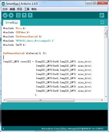
打开Arduino IDE编程软件,点击 【文件】->【打开】,打开插卡音箱文件夹后选择Microduino_Audio_ble\ SmartEgg.ino | 打开Arduino IDE编程软件,点击 【文件】->【打开】,打开插卡音箱文件夹后选择Microduino_Audio_ble\ SmartEgg.ino | ||
| − | [[File:Eggdl1.jpg|| | + | [[File:Eggdl1.jpg||450px|center]] |
点击"√",编译程序。 | 点击"√",编译程序。 | ||
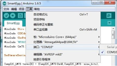
点击【工具】,选择正确的板+处理器+端口。 | 点击【工具】,选择正确的板+处理器+端口。 | ||
点击"→",进行上传。 | 点击"→",进行上传。 | ||
| − | [[File:Eggdl2.jpg|| | + | [[File:Eggdl2.jpg||450px|center]] |
==组装== | ==组装== | ||
*'''Step1''':拼装时首先确认外壳物料是否齐全。 | *'''Step1''':拼装时首先确认外壳物料是否齐全。 | ||
| − | [[File:Eggstr1.jpg|| | + | [[File:Eggstr1.jpg||800px|center]] |
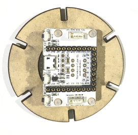
*'''Step2''':之后将Cube-S1底板固定在底板上,如图所示 | *'''Step2''':之后将Cube-S1底板固定在底板上,如图所示 | ||
| − | [[File:Eggstr2.jpg|| | + | [[File:Eggstr2.jpg||450px|center]] |
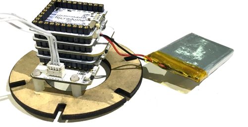
*'''Step3''':之后将Core+,BM,BT,10DOF插接好(无上下顺序),并插在Cube-S1底板上。将锂电池连接在BM模块的接口上。 | *'''Step3''':之后将Core+,BM,BT,10DOF插接好(无上下顺序),并插在Cube-S1底板上。将锂电池连接在BM模块的接口上。 | ||
| − | [[File:Eggstr3.jpg|| | + | [[File:Eggstr3.jpg||500px|center]] |
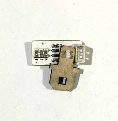
*'''Step4''':将传感器与传感器固定的木片使用螺丝固定好,如图所示 | *'''Step4''':将传感器与传感器固定的木片使用螺丝固定好,如图所示 | ||
[[File:Eggstr4.jpg||500px|center]] | [[File:Eggstr4.jpg||500px|center]] | ||
| 第86行: | 第86行: | ||
[[File:Eggstr9.JPG||500px|center]] | [[File:Eggstr9.JPG||500px|center]] | ||
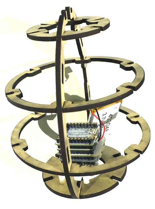
至此鸟蛋部分拼装完成 | 至此鸟蛋部分拼装完成 | ||
| + | |||
==mCotton设置== | ==mCotton设置== | ||
进入https://mcotton.microduino.cn/projects | 进入https://mcotton.microduino.cn/projects | ||
| 第104行: | 第105行: | ||
[[File:Eggcotton7.jpg||450px|center]] | [[File:Eggcotton7.jpg||450px|center]] | ||
| − | + | ==手机中继== | |
| + | 点开手机APP进入如下界面 | ||
| + | [[File:Eggphone1.jpg||550px|center]] | ||
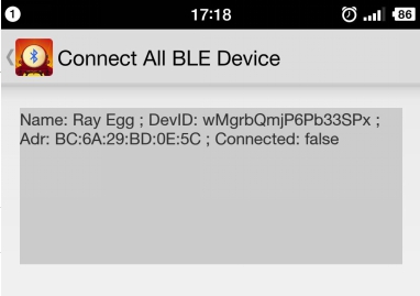
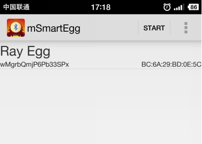
| + | 图上会显示的是既存的项目信息,Connected为手机与mCotton间的通讯状态,后面的true/false为鸟蛋与手机蓝牙的链接状态。 | ||
| + | 之后点击右上角Start按钮进入下一步,此时点击右上角的按钮,并选择Add Device | ||
| + | [[File:Eggphone2.jpg||550px|center]] | ||
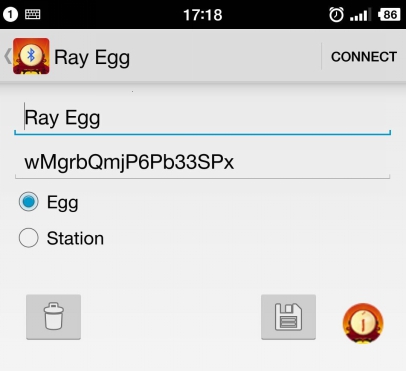
| + | 输入名称与mCotton步骤中记录的项目ID之后点击右上角的CONNECT按钮。 | ||
| + | [[File:Eggphone3.jpg||550px|center]] | ||
| + | 至此手机中继部分设置完成。 | ||
| + | 全部步骤都已完成,观察手机中继部分,状态是否为Connect,true。如果是则可以开始观察网页以观测数据了。 | ||
==操作说明== | ==操作说明== | ||
| − | |||
==程序说明== | ==程序说明== | ||
| − | |||
<source lang = "cpp"> | <source lang = "cpp"> | ||
| − | + | #include <Wire.h> | |
| − | + | #include <I2Cdev.h> | |
| − | + | #include <SoftwareSerial.h> | |
| − | + | #include "MPU6050_6Axis_MotionApps20.h" | |
| − | + | #include <lm75.h> | |
| − | + | ||
| − | + | SoftwareSerial bleSerial(4, 5); | |
| − | + | ||
| − | + | TempI2C_LM75 termo[8] = {TempI2C_LM75(0x48, TempI2C_LM75::nine_bits), | |
| − | + | TempI2C_LM75(0x49, TempI2C_LM75::nine_bits), | |
| − | + | TempI2C_LM75(0x4A, TempI2C_LM75::nine_bits), | |
| − | + | TempI2C_LM75(0x4B, TempI2C_LM75::nine_bits), | |
| − | + | TempI2C_LM75(0x4C, TempI2C_LM75::nine_bits), | |
| − | + | TempI2C_LM75(0x4D, TempI2C_LM75::nine_bits), | |
| − | + | TempI2C_LM75(0x4E, TempI2C_LM75::nine_bits), | |
| − | + | TempI2C_LM75(0x4F, TempI2C_LM75::nine_bits) | |
| − | + | }; | |
| − | + | ||
| − | + | Quaternion q; | |
| − | + | MPU6050 mpu; | |
| − | + | uint8_t mpuIntStatus; | |
| − | + | uint16_t packetSize; | |
| − | + | uint16_t fifoCount; | |
| − | + | ||
| − | + | uint8_t fifoBuffer[64]; // FIFO存储缓冲器 | |
| − | + | float buff1[10]; //发送数据缓存 | |
| − | + | ||
| − | + | unsigned long time_mpu, time_tem; | |
| − | + | ||
| − | + | uint8_t devStatus; | |
| − | + | ||
| − | + | //获取四元数 | |
| − | + | void dmpGetQuaternion() | |
| − | + | { | |
| − | + | mpuIntStatus = mpu.getIntStatus(); | |
| − | + | fifoCount = mpu.getFIFOCount(); | |
| − | + | if((mpuIntStatus & 0x10) || fifoCount == 1024) | |
| − | + | { | |
| − | + | mpu.resetFIFO(); | |
| − | + | } | |
| − | + | else if(mpuIntStatus & 0x02) | |
| − | + | { | |
| − | + | while (fifoCount < packetSize) fifoCount = mpu.getFIFOCount(); | |
| − | + | mpu.getFIFOBytes(fifoBuffer, packetSize); | |
| − | + | fifoCount -= packetSize; | |
| − | + | mpu.dmpGetQuaternion(&q, fifoBuffer); | |
| − | + | // mpu.resetFIFO(); | |
| − | + | } | |
| − | + | ||
| − | + | } | |
| − | + | ||
| − | + | void setup() | |
| − | + | { | |
| − | + | Serial.begin(9600); | |
| − | + | bleSerial.begin(9600); | |
| − | + | Wire.begin(); | |
| − | + | mpu.initialize(); | |
| − | + | ||
| − | + | Serial.println("Testing device connections..."); | |
| − | + | Serial.println(mpu.testConnection() ? "MPU6050 connection successful" : "MPU6050 connection failed"); | |
| − | + | ||
| − | + | Serial.println(F("Initializing DMP...")); | |
| − | + | devStatus = mpu.dmpInitialize(); | |
| − | + | if(devStatus == 0) | |
| − | + | { | |
| − | + | Serial.println(F("Enabling DMP...")); | |
| − | + | mpu.setDMPEnabled(true); | |
| − | + | mpuIntStatus = mpu.getIntStatus(); | |
| − | + | packetSize = mpu.dmpGetFIFOPacketSize(); | |
| − | + | } | |
| − | + | else | |
| − | + | { | |
| − | + | while(1) | |
| − | + | { | |
| − | + | Serial.print(F("DMP Initialization failed (code ")); | |
| − | + | Serial.print(devStatus); | |
| − | + | Serial.println(F(")")); | |
| − | + | } | |
| − | + | } | |
| − | + | ||
| − | + | } | |
| − | + | ||
| − | + | void loop() | |
| − | + | { | |
| − | + | dmpGetQuaternion(); | |
| − | + | if(millis() > time_mpu + 1000) | |
| − | + | { | |
| − | + | time_mpu = millis(); | |
| − | + | buff1[0] = q.w; | |
| − | + | buff1[1] = q.x; | |
| − | + | buff1[2] = q.y; | |
| − | + | buff1[3] = q.z; | |
| − | + | /* | |
| − | + | Serial.print("quat\t"); | |
| − | + | Serial.print(q.w); | |
| − | + | Serial.print("\t"); | |
| − | + | Serial.print(q.x); | |
| − | + | Serial.print("\t"); | |
| + | Serial.print(q.y); | ||
| + | Serial.print("\t"); | ||
| + | Serial.println(q.z); | ||
| + | */ | ||
| + | sendData(0xAA, 16, (uint8_t *)buff1); | ||
| + | } | ||
| + | |||
| + | if(millis() > time_tem + 5000) | ||
| + | { | ||
| + | time_tem = millis(); | ||
| + | for(int i = 0; i < 8; i++) | ||
| + | { | ||
| + | buff1[i] = termo[i].getTemp(); | ||
| + | Serial.print(buff1[i]); | ||
| + | Serial.print(","); | ||
| + | } | ||
| + | Serial.println(" "); | ||
| + | sendData(0xBB, 32, (uint8_t *)buff1); | ||
| + | } | ||
| + | } | ||
| + | |||
| + | void sendData(uint8_t cmd, int _num, uint8_t *_buf) | ||
| + | { | ||
| + | uint8_t sendBuf[40]; | ||
| + | |||
| + | sendBuf[0] = 0xAA; | ||
| + | sendBuf[1] = 0xBB; | ||
| + | sendBuf[2] = cmd; | ||
| + | if(_num > 0) | ||
| + | memcpy(sendBuf + 3, _buf, _num); | ||
| + | sendBuf[_num+3] = 0x0d; | ||
| + | sendBuf[_num+4] = 0x0a; | ||
| + | |||
| + | bleSerial.write(sendBuf, _num + 5); | ||
| + | } | ||
| − | |||
| − | |||
| − | |||
| − | |||
| − | |||
| − | |||
| − | |||
| − | |||
| − | |||
| − | |||
</source> | </source> | ||
==视频== | ==视频== | ||
2016年2月16日 (二) 03:33的最新版本
概述
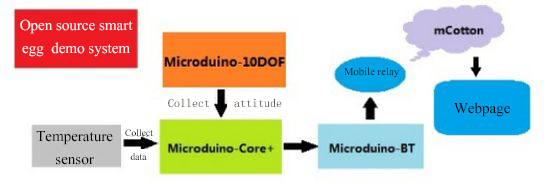
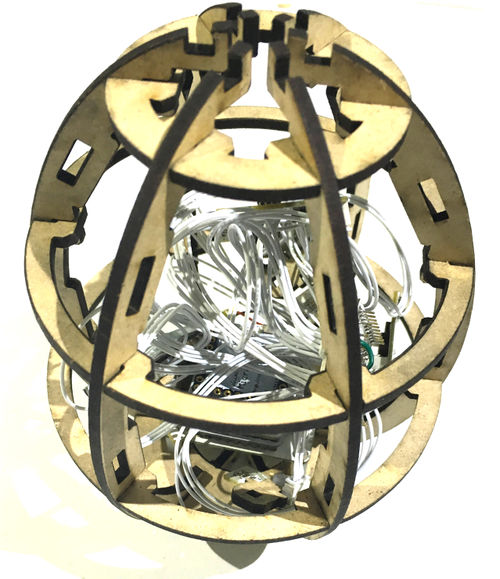
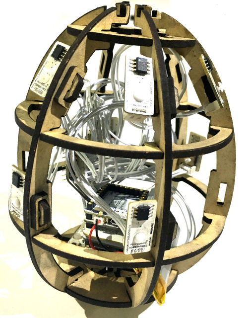
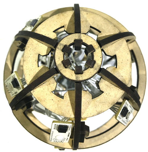
本次教程我们将使用Microduino产品模块搭建鸟蛋温度检测系统,该系统通过温度传感器采集鸟蛋中各个点的内容,同时将数据传到手机中,实时生成温度表示图。 材料清单
实验原理智能鸟蛋系统主要由两大部分组成,数据采集部分由8个LM75温度传感器和一个10DOF模块组成,实时采集鸟蛋多个位置的温度和鸟蛋的位置状态,之后经过核心Core+的处理通过蓝牙模块Microduino-BT与手机联动将数据传输到手机中继上,继而上传到我们的云服务器mCotton,之后可通过网页查看温度示意图和鸟蛋姿态示意图。
Microduino-LM75 Microduino-Module Motion/zh 文档鸟蛋代码:【鸟蛋演示系统代码】 鸟蛋代码Github:SmartEgg 调试过程将Microduino-Core+/zh、Microduino-USBTTL/zh堆叠在一起.用数据线将写好的程序通过Microduino-USBTTL/zh上传到Microduino-Core+/zh上。 注意:最好不要将所有模块堆叠在一起之后再上传程序 打开Arduino IDE编程软件,点击 【文件】->【打开】,打开插卡音箱文件夹后选择Microduino_Audio_ble\ SmartEgg.ino 点击"√",编译程序。 点击【工具】,选择正确的板+处理器+端口。 点击"→",进行上传。 组装
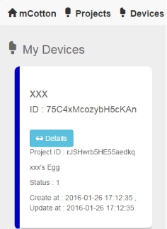
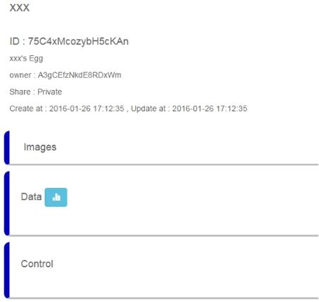
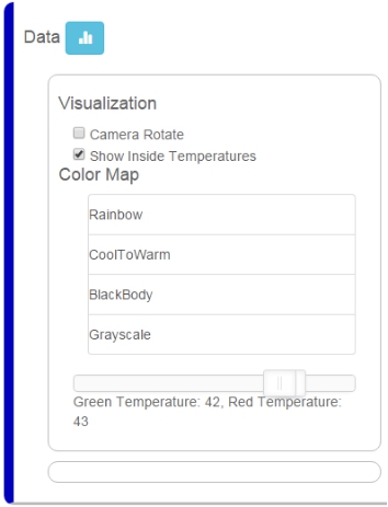
至此鸟蛋部分拼装完成 mCotton设置进入https://mcotton.microduino.cn/projects 点击右上角Sign in/Join,在下拉菜单中点击右下角的Create account创建自己的账号。 输入Email作为用户名和自己的密码,之后点击Create即可。 注册后会自动进入登录状态,若未登录则点击右上角Sign in输入用户名(邮箱)和密码登录。登陆后点击左上角的Projects。 此时网页上会显示很多个标签,找到Smart Egg标签,并点击Made It进入下一步页面 在此处填写自己项目的名称和项目描述。图中高亮部分ID需要记住,建议复制在txt中保存。之后点击√Save 之后进入myDevice页面,会看到出现了名为XXX(刚才设定好的名字)的项目,点Details进入详细页面。 在之后的页面中点击Data右边的蓝色图标进入数据观察页面 若连接成功则右侧可显示鸟蛋数据图,左侧为选项设置部分 手机中继点开手机APP进入如下界面 图上会显示的是既存的项目信息,Connected为手机与mCotton间的通讯状态,后面的true/false为鸟蛋与手机蓝牙的链接状态。 之后点击右上角Start按钮进入下一步,此时点击右上角的按钮,并选择Add Device 输入名称与mCotton步骤中记录的项目ID之后点击右上角的CONNECT按钮。 至此手机中继部分设置完成。 全部步骤都已完成,观察手机中继部分,状态是否为Connect,true。如果是则可以开始观察网页以观测数据了。 操作说明程序说明#include <Wire.h>
#include <I2Cdev.h>
#include <SoftwareSerial.h>
#include "MPU6050_6Axis_MotionApps20.h"
#include <lm75.h>
SoftwareSerial bleSerial(4, 5);
TempI2C_LM75 termo[8] = {TempI2C_LM75(0x48, TempI2C_LM75::nine_bits),
TempI2C_LM75(0x49, TempI2C_LM75::nine_bits),
TempI2C_LM75(0x4A, TempI2C_LM75::nine_bits),
TempI2C_LM75(0x4B, TempI2C_LM75::nine_bits),
TempI2C_LM75(0x4C, TempI2C_LM75::nine_bits),
TempI2C_LM75(0x4D, TempI2C_LM75::nine_bits),
TempI2C_LM75(0x4E, TempI2C_LM75::nine_bits),
TempI2C_LM75(0x4F, TempI2C_LM75::nine_bits)
};
Quaternion q;
MPU6050 mpu;
uint8_t mpuIntStatus;
uint16_t packetSize;
uint16_t fifoCount;
uint8_t fifoBuffer[64]; // FIFO存储缓冲器
float buff1[10]; //发送数据缓存
unsigned long time_mpu, time_tem;
uint8_t devStatus;
//获取四元数
void dmpGetQuaternion()
{
mpuIntStatus = mpu.getIntStatus();
fifoCount = mpu.getFIFOCount();
if((mpuIntStatus & 0x10) || fifoCount == 1024)
{
mpu.resetFIFO();
}
else if(mpuIntStatus & 0x02)
{
while (fifoCount < packetSize) fifoCount = mpu.getFIFOCount();
mpu.getFIFOBytes(fifoBuffer, packetSize);
fifoCount -= packetSize;
mpu.dmpGetQuaternion(&q, fifoBuffer);
// mpu.resetFIFO();
}
}
void setup()
{
Serial.begin(9600);
bleSerial.begin(9600);
Wire.begin();
mpu.initialize();
Serial.println("Testing device connections...");
Serial.println(mpu.testConnection() ? "MPU6050 connection successful" : "MPU6050 connection failed");
Serial.println(F("Initializing DMP..."));
devStatus = mpu.dmpInitialize();
if(devStatus == 0)
{
Serial.println(F("Enabling DMP..."));
mpu.setDMPEnabled(true);
mpuIntStatus = mpu.getIntStatus();
packetSize = mpu.dmpGetFIFOPacketSize();
}
else
{
while(1)
{
Serial.print(F("DMP Initialization failed (code "));
Serial.print(devStatus);
Serial.println(F(")"));
}
}
}
void loop()
{
dmpGetQuaternion();
if(millis() > time_mpu + 1000)
{
time_mpu = millis();
buff1[0] = q.w;
buff1[1] = q.x;
buff1[2] = q.y;
buff1[3] = q.z;
/*
Serial.print("quat\t");
Serial.print(q.w);
Serial.print("\t");
Serial.print(q.x);
Serial.print("\t");
Serial.print(q.y);
Serial.print("\t");
Serial.println(q.z);
*/
sendData(0xAA, 16, (uint8_t *)buff1);
}
if(millis() > time_tem + 5000)
{
time_tem = millis();
for(int i = 0; i < 8; i++)
{
buff1[i] = termo[i].getTemp();
Serial.print(buff1[i]);
Serial.print(",");
}
Serial.println(" ");
sendData(0xBB, 32, (uint8_t *)buff1);
}
}
void sendData(uint8_t cmd, int _num, uint8_t *_buf)
{
uint8_t sendBuf[40];
sendBuf[0] = 0xAA;
sendBuf[1] = 0xBB;
sendBuf[2] = cmd;
if(_num > 0)
memcpy(sendBuf + 3, _buf, _num);
sendBuf[_num+3] = 0x0d;
sendBuf[_num+4] = 0x0a;
bleSerial.write(sendBuf, _num + 5);
}
视频 |
