“光照指示器”的版本间的差异
853387039@qq.com(讨论 | 贡献) |
|||
| 第32行: | 第32行: | ||
[[File:CoreUSB_Ble_pc.jpg|600px|center]] | [[File:CoreUSB_Ble_pc.jpg|600px|center]] | ||
*Setup 2:下载程序: [https://github.com/Microduino/Microduino_Tutorials/blob/master/MCookie_Tutorial/light_led/light_led.ino light_led] | *Setup 2:下载程序: [https://github.com/Microduino/Microduino_Tutorials/blob/master/MCookie_Tutorial/light_led/light_led.ino light_led] | ||
| − | [[File: light_indicator- | + | [[File: light_indicator-load.jpg|600px|center]] |
* Setup 3:加载代码,将程序代买拷贝到IDE中。程序编译通过后选择好板卡和COM端口下载程序。 | * Setup 3:加载代码,将程序代买拷贝到IDE中。程序编译通过后选择好板卡和COM端口下载程序。 | ||
==程序说明== | ==程序说明== | ||
2015年10月12日 (一) 06:09的版本
| Language | English |
|---|
目的做一个的光照指示器,将光值分为三个等级,通过绿、蓝、红三种颜来反应光的强弱。 原理通过Light光线传感器检测光的强弱,系统判断光强在定义的哪个范围区间,对应让彩灯亮不同颜色,同时,在同一区间内光越强,颜色越亮。 设备
准备
程序说明
#define PIN 6
Adafruit_NeoPixel strip = Adafruit_NeoPixel(1, PIN, NEO_GRB + NEO_KHZ800);

#define Light_PIN A0
#define Light_value1 400
#define Light_value2 800
sensorValue = analogRead(Light_PIN);
if (sensorValue < Light_value1)
    colorWipe(strip.Color(0, map(sensorValue, 10, 400, 0, 255), 0));
  else if (sensorValue >= Light_value1 && sensorValue < Light_value2)
    colorWipe(strip.Color(0, 0, map(sensorValue, 400, 800, 0, 255)));
  else if (Light_value2 >= 800)
    colorWipe(strip.Color(map(sensorValue, 800, 960, 0, 255), 0, 0));
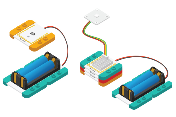
搭建硬件
结果改变光的环境,光从暗到亮颜色依次变化为绿-蓝-红,并且光越弱,亮度越低。 你也可以通过乐高搭建一个漂亮的外观。 视频 |
