|
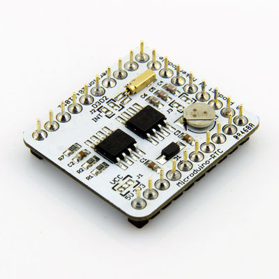
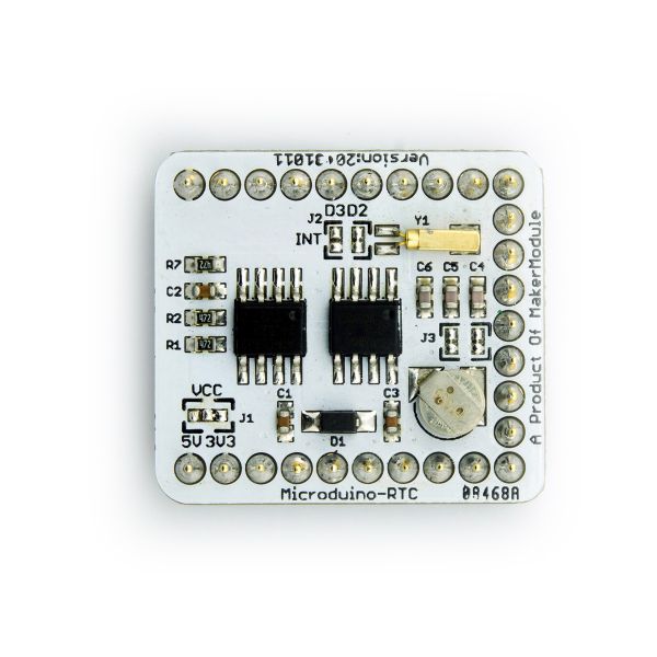
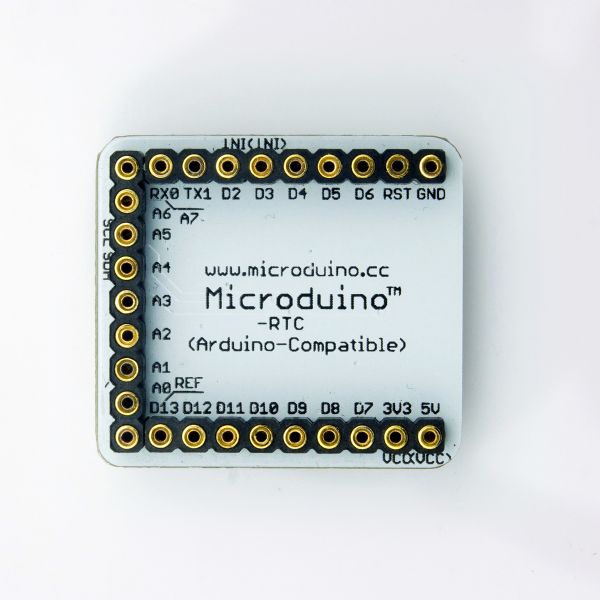
Microduino-RTC Module is a Real Time Clock module based on NXP CMOS PCF8563. RTC module uses TWI/I2C interface for communication. Data can be backed up with the addtional AT24c32 EEPROM. With an onboard capacitor, RTC module keeps time for serveral minutes after power disconnected. PCF8563 uses external crystal, and can provide timer intterupt tigger.
- Microduino RTC Real Time Clock Module
- PCF8563 CMOS Real-Time Clock (RTC)
- Two Wire Interface (I2C)
- Backup by additional EEPROM AT24C32
|
Feature
- Based on PCF8563 clock chip with century mark, seconds, minutes, hours, day, week, month, year;
- Use the I2C interface to communicate with the Core/Core+ module;
- Use EEPROM AT24C32 with I2C interface;
- Low-power clock chip, the typical current value 0.25μA, plus a super capacitor, the clock is still running after a power diconnect;
- Open source hardware circuit design, compatible with the Arduino IDE development environment for programming;
- Define unified interface Microduino specification and contain rich peripheral modules. Set up the quick connection with other Microduino modules and sensors easily and flexibly.
- 2.54 pitch row female connector for easy integration into breadboard.
|
Specification
- Clock chip: PCF8563;
- Low-power CMOS real-time clock/calendar chip;
- Provides a programmable clock output, an interrupt output and a brown-out detector, transfers all address and data via the I2C serial bus interface;
- The maximum bus speed is 400Kbits/s, after read and write data, the embedded word address register is automatically generated increment.
- EEPROM chip:AT24C32
- Provide 32,768 serial electrically EPROM, organized as 4096 words × 8-bit length;。
- Cascade feature allows AT24C32 articulated eight devices on the same I2C bug, the replication cycle of millions lives and saved the data to 100 years with a write-protect function.
- Super capacitor:XH414
- Provide a power-down timing function in a time slot。
Document
Eagle PCB Download
Main components
Development
Arduino library and supported package
Application
Software Download
- Prepared hardware:Microduino FT232R、Microduino Core、Microduino RTC、Microduino OLED;
- Prepared software:Microduino provides test program(Arduino part)、Arduino IDE(1.0 release upper)、Rtc_Pcf8563 library;
- Put the downloaded library to the library folder of Arduino IDE installation folder;
- Start Arduino IED,open the test program that Microduino provides,card type choose the "Microduino Core (Atmega328P@16M,5V)",then download directly.
Test the continued time after power down:[RTC_Time]
- Boot display the loading process,including:Welcome!Load Time...,Microduino logo,load a project about every 1s. Finished loading, enter into the main program page.
- The first line displays the date, the format is xx/xx/xx(year/month/day);
- The second line displays the time, and week. The time format: xx:xx:xx(Hour:minute:second), followed the week(English format,excluding abbreviations);
- The third line fixed displays that:"Microduino-RTC v1.0 201310". Using a small font because of the characters more;
- After program running, disconnect the power. Wait for a moment, you can see the Time on the second line that is the continued time instead of default set time;
- (Note:RTC is a programmable clock output module,use function vosettime() to set time. After the download is completed, need commented vosettime () function to power down and then continue the next time, or else once the power restarts,recover the set value too)
Test EEPROM read/write:[RTC_EEPROM]
- Boot display the loading process,including:Welcome!,Load EEPROM,Microduino logo,load a project about every 1s. Finished loading, enter into the main program page;
- The first line displays the random function values,the first value is a random number from 10 to 99, the second value is the read value power recovered after last power down;
- The second line fixed displays that:"Microduino-RTC v1.0 201310". Using a small font because of the characters more;
- During the test, unplug the power firstly and then plug in the power, you can see the last value prior to power-down transformation of random numbers read EEPROM updates to display the value of place.
Test timer interrupt:[RTC_Alarm]
- Boot display the loading process,including:Welcome!,Load Time...,Load Alarm..,Microduino logo,load a project about every 1s. Finished loading, enter into the main program page;
- The first line display the time. Time format: xx:xx:xx(Hour:minute:second);
- The second line fixed displays that:"Microduino-RTC v1.0 201310". Using a small font because of the characters more;
- Timer interrupt,when the time reaches the set time, led flashes once per second,lasts 1 minute, and you can see the countdown time on the OLED screen
|


