Outline
- Project:Microduino Self-balance Robot
- Purpose:To control the self-balance robot by Microduino-Joypad.
- Difficulty: High
- Time-consuming: 6-hour
- Maker: Microduino Studio-PKJ
Introduction
By using gyroscope and accelerometer (Microduino-10DOF) to detect altitude change of the robot, and ([[Microduino-Stepper) to drive the motor precisely and keep the balance of the system.
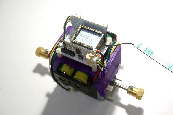
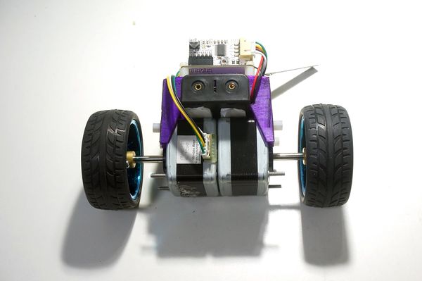
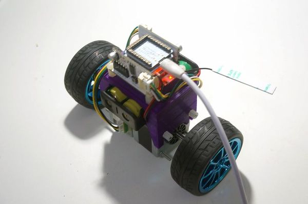
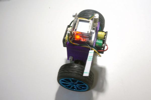
The robot is simply structured with a self-designed 3D-printer frame and a stepper as well as a self-balance system to adjust.
It is highly integrated with less wires and powerful modules, which adopts Nrf24 for wireless communication currently. Users can change communication option according to personal preference.
Frame Buildup and Debugging
Equipment
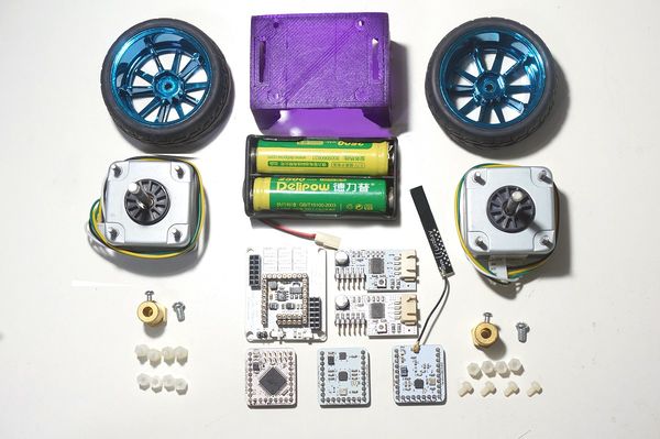
- Microduino modules needed
| Module |
Number |
Function
|
| Stepper |
2 |
Keep wheels running
|
| Wheel |
2 |
|
| 18650 Battery box |
1 |
Battery loading
|
| 18650 Battery |
2 |
Power supply
|
| 3D printer frame |
1 |
Frame support
|
| Plastic fastener |
12 |
Fixate the frame
|
Robot Buildup
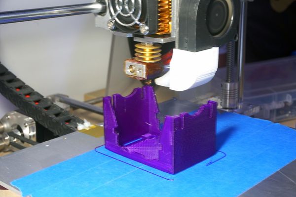
- Step 1:Build the model by GoogleSketchUp and print out the model with 3D printer
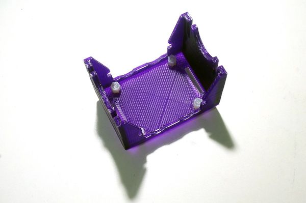
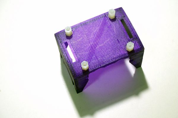
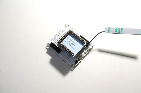
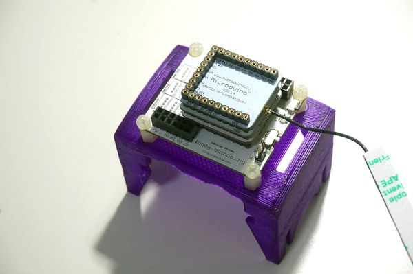
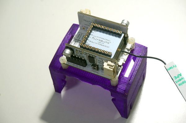
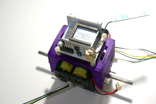
- Step 2: Put four single-pass and double-pass on the 3D printer frame to fixate Microduino-Robot.
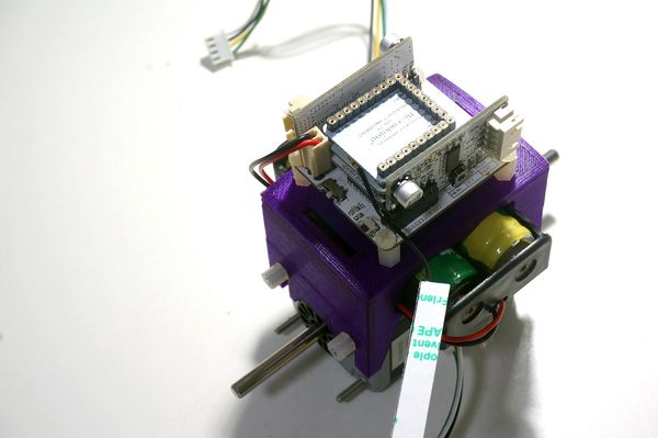
- Step 4: Fixate the installed boards on the frame with the nylon strings.
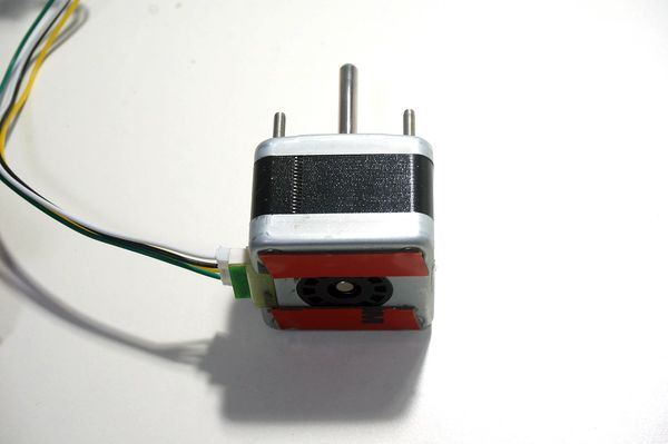
- Step 6: Stick the double-sided adhesive on the bottom of the stepper to strengthen it.
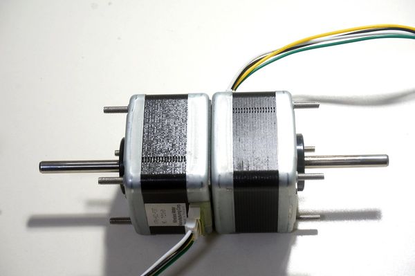
- Step 7: Install the two steppers together.
- Step 8: Fixate the battery.
- Step 9: Connect the power interface of the battery to the board. You can check whether the power supply works normally or not by switching on the power of Microduino-Robot.
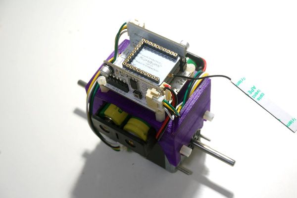
- Step 10: Wiring method of the stepper connector. Take M.B drive interface for example, the left motor connects to Microduino-Stepper and the left one to M.A
- Step 11: Fixate the metal post on the stepper.
- Step 12: Fixate the wheel on the metal post.
Then, the whole structure buildup is finished.
Software Debugging
You will need_03_Microduino_nRF_RF24 and _03_Microduino_nRF_RF24Network and please replace the original Arduino IDE libraries.
https://github.com/Microduino/Microduino_Tutorials/tree/master/Microduino_Joypad/Joypad_Balance_Reception
- Debugging:
- Preparation
- Hardware: Microduino-USBTTL and the well-built self-balance robot.
- Software: Libraries supported and Arduino IDE;
- Uncompress the library files and test program and then copy them to library folder in Arduino IDE;
- Open the program and select Microduino Core+(Atmega644P@16M,5V) as the board after compiling, then stack Microduino-USBTTL and upload directly;
- After the upload, you can take off Microduino-USBTTL and turn on the power switch. Take the robot for about 4 seconds and then loose your hands and watch if it can stand up.
- You can try to disturb the robot with your hands and can feel the counterforce.
Remote Controller (Microduino-Joypad) Buildup
Here we adopt Microduino-Joypad as the remote controller. Off course, you also other modules to build it.
Equipment Requirement
| Module |
Number |
Function
|
| USB cable |
1 |
Data transmission
|
| Battery box |
1 |
Battery loading
|
| 7th dry battery |
3 |
Power supply
|
Hardware Buildup
- Step 1: Install Microduino-TFT on the panel of Microduino-Joypad;
- Step 2: Install nylon fastener on Microduino-Joypad and stick the base panel on the bottom of Microduino-Joypad;
- Step 3: Connect Microduino-TFT and Microduino-Joypad through wires;
- Step 4: Connect the battery on the base board and notice the electrode which you can see on the back of the board.
- Step 5: Fixate the base board and the panel with nylon fasteners;
- Step 6: You can turn on the power switch and watch whether the power supply works fine.
Software Debugging
You will need libraries below: _01_Microduino_GFX, _01_Microduino_TFT_ST7735 and _08_Microduino_Shield_Joypad;Please replace the original Arduino IDE libraries.
- Open the program and choose the right board for download after compiling, and then have an overall configuration after the download.
- Turn on the power switch of the remote controller and press the reset key and enter the system. Please press the key A in 4 seconds and enter the adjustment mode of the remote controller.
- Rotate two joysticks to the fullest and press key 3 and enter Robot control mode after seeing no data change on TFT screen.
- The left switch is OutPutEnable and only when you turn it upside can you control the robot. The left joystick controls back and forth rotation, and the right joystick controls left and right-direction rotation.
Attention
- Keep the electrode correct. Otherwise, it may cause circuit burn.
*Please first adjust the remote controller or it may lead to false control.
- The wire connection of Microduino-Stepper should be correct. If you find it cannot work, please change and try again.
|
