“控制led亮度”的版本间的差异
(→调试) |
(→程序) |
||
| 第29行: | 第29行: | ||
见 LEDBrightness | 见 LEDBrightness | ||
| + | 注意:代码里包含图片请不要丢掉 | ||
==调试== | ==调试== | ||
2014年5月5日 (一) 08:38的版本
目的本教程将教大家如何用Processing来控制LED灯的亮度。 设备
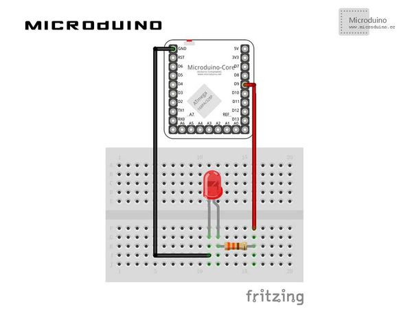
原理图
程序见 LEDBrightness 注意:代码里包含图片请不要丢掉 调试步骤一:解释一下代码: void draw() {
loadPixels();
// We must also call loadPixels() on the PImage since we are going to read its pixels. img.loadPixels();
for (int x = 0; x < img.width; x++ ) {
for (int y = 0; y < img.height; y++ ) {
// Calculate the 1D pixel location
int loc = x + y*img.width;
// Get the R,G,B values from image
float r = red (img.pixels[loc]);
float g = green (img.pixels[loc]);
float b = blue (img.pixels[loc]);
// We calculate a multiplier ranging from 0.0 to 8.0 based on mouseX position.
// That multiplier changes the RGB value of each pixel.
float adjustBrightness = ((float) mouseX / width) * 8.0;
r *= adjustBrightness;
g *= adjustBrightness;
b *= adjustBrightness;
// The RGB values are constrained between 0 and 255 before being set as a new color.
r = constrain(r,0,255);
g = constrain(g,0,255);
b = constrain(b,0,255);
// Make a new color and set pixel in the window
color c = color(r,g,b);
pixels[loc] = c;
}
}
updatePixels();
//output r value to ledpin
arduino.digitalwrite(ledPin, r);
}
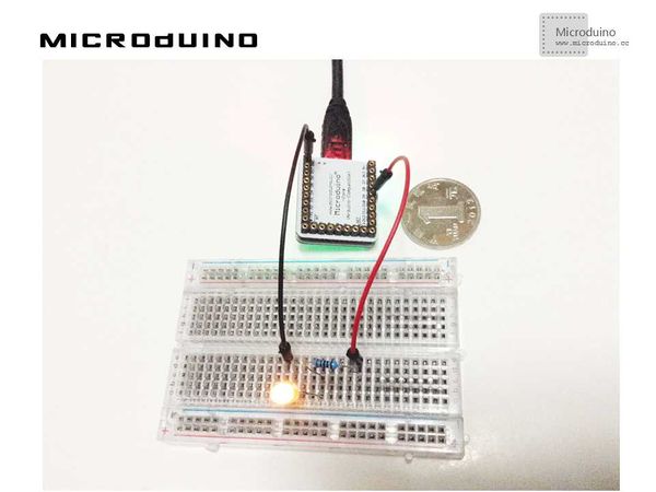
步骤二:按着原理图搭建硬件环境,像这样:
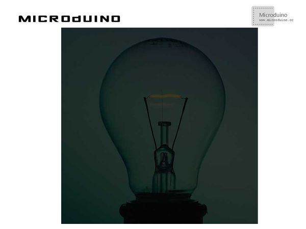
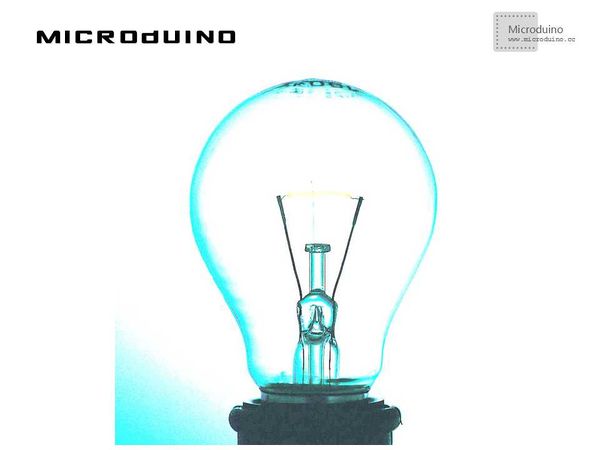
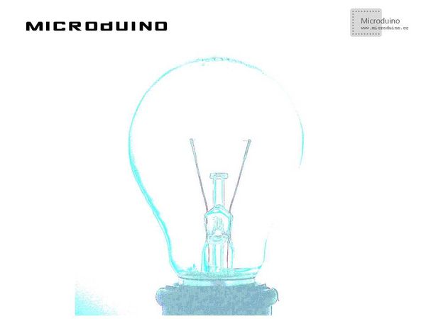
结果鼠标在左边灯泡最暗,在右边最亮,随着从左到右逐渐变化,processing的效果是这样的。 鼠标在左边: 鼠标在中间: 鼠标在右边:
视频 |
