“Microduino Digital Oscilloscope”的版本间的差异
(Created page with "{| style="width: 800px;" |- | ==Purpose== The course will show you how to use Microduino to make a digital oscilloscope. ==Source== From: http://www.arduino.cn/thread-37...") |
小 (Wasdpkj@hotmail.com moved page Microduio Digital Oscilloscope to Microduino Digital Oscilloscope) |
(没有差异)
| |
2016年1月6日 (三) 02:19的最新版本
|
PurposeThe course will show you how to use Microduino to make a digital oscilloscope. SourceFrom: http://www.arduino.cn/thread-3703-1-1.html Equipment
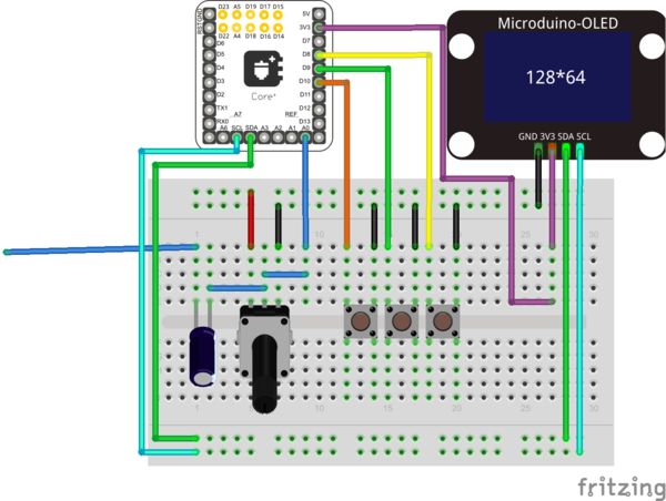
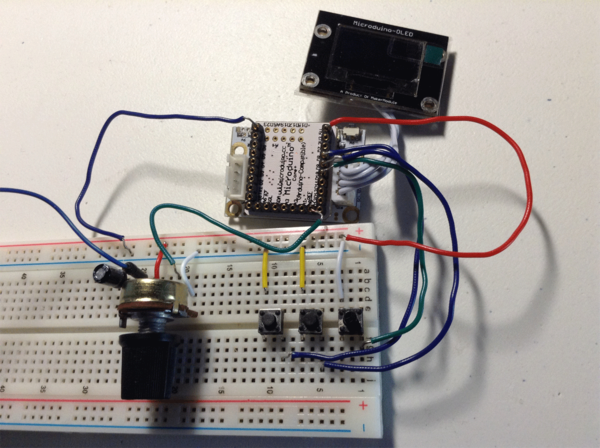
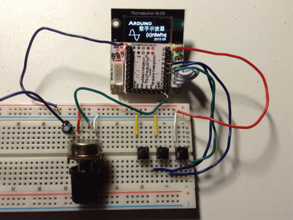
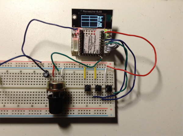
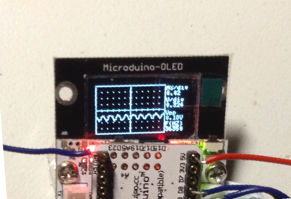
IntroductionHere in this example, we’ll introduce a Microduino digital oscilloscope. Main parameters: Frequency response: 10Hz-50KHz Power: 5V Microduino-OLED display screen: 128x64 Display area: 96x64 Message display area: 32x64 (Frequency of testing signal and Vpp.) Way of synchronization: Rising along the trigger Scanning speed: 0.02ms/div~10ms/div (Classified by nine gears according to 1-2-5 carry.) Hold Function: Freeze waveform display and parameters. SchematicProgramDebuggingStep 1: Build the circuit according to the schematic, as follows: Step 2: Download the code, compile and run initial screen: Step 3: Just use sensing point to contact signal and input circuit, you will see waveform displayed on OLED: Step 4: The three keys in the schematic are used for enlarging and reducing the scaleplate of the displayed waveform and served as “OK” button respectively. ResultSignal waveform can be displayed on OLED. Video |
