“Sensor-Relay/zh”的版本间的差异
| (未显示2个用户的6个中间版本) | |||
| 第1行: | 第1行: | ||
| − | |||
{| style="width: 800px;" | {| style="width: 800px;" | ||
|- | |- | ||
| − | | | + | |[[File: Microduino-Relay.jpg|300px|left|Sensor-Relay]] || |
| − | [[File: Microduino-Relay.jpg| | + | ::<p style="color: #000000;font-size:200%"><br><br><br><br><br>'''Sensor-Relay'''</p> |
| + | ::产品编号:'''<big style="color: #00A0A6">MSDO11</big>''' | ||
| + | |- | ||
| + | |[[File: Add-to-cart.jpg|300px|left|link=https://shop108263663.taobao.com/?spm=a230r.7195193.1997079397.2.ek3cAW]]|| | ||
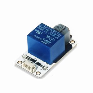
| + | ::<p style="color: #000000;font-size:120%">Sensor-Relay是继电器模块,可用于隔离控制。 | ||
| + | </p> | ||
| + | |} | ||
| + | <br> | ||
| + | <br> | ||
| + | {| style="width: 800px;" | ||
| + | <p style="color: #333333;font-size:155%">'''技术规格'''</p> | ||
| + | {| class="wikitable" | ||
| + | |- | ||
| + | | '''原边输入'''||5V | ||
| + | |- | ||
| + | | '''副边输出'''||10A 250VAC/10A 30VDC | ||
| + | |- | ||
| + | | '''接口'''||D2~D13,A0~A7 | ||
| + | |- | ||
| + | | '''接口'''||1.27mm间距的4Pin座 | ||
| + | |- | ||
| + | | '''特色'''||可隔离控制高电压、大电流信号,体积小,易安装 | ||
| + | |} | ||
| + | <br> | ||
| + | ---- | ||
| + | <br> | ||
| + | <p style="color: #333333;font-size:155%">'''引脚'''</p> | ||
| + | {| border="0" cellpadding="10" width="90%" | ||
| + | |- | ||
| + | |width="35%" valign="center" align="left"| | ||
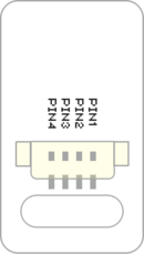
| + | *IN'''<big style="color: #00A0A6">(数字信号)</big>''' | ||
| + | **PIN1:GND | ||
| + | **PIN2:VCC | ||
| + | **PIN3:数字信号输出 | ||
| + | **PIN4:NC(空) | ||
| + | |width="35%" valign="top" align="center"| | ||
| + | [[file: Sensor_backpin.png|130px|center]] | ||
| + | |width="25%" valign="top" align="center"| | ||
| + | |} | ||
| + | <br> | ||
| + | ---- | ||
| + | <br> | ||
| + | <p style="color: #333333;font-size:135%">'''编程手册'''</p> | ||
| + | 您可通过[[AVR核心:Getting_started/zh|Getting Started]]了解使用Arduino IDE编程控制模块。 | ||
| + | <p style="color: #333333;font-size:120%">'''普通用法'''</p> | ||
| + | *1、将核心模块和传感器接口模块堆叠在电池盒模块上。 | ||
| + | *2、将继电器传感器通过排线接到传感器接口模块的6/7管脚上。 | ||
| + | *3、将USB连接线一段插入电池盒模块,另一端连接PC电脑,并打开电池盒模块的电源开关。 | ||
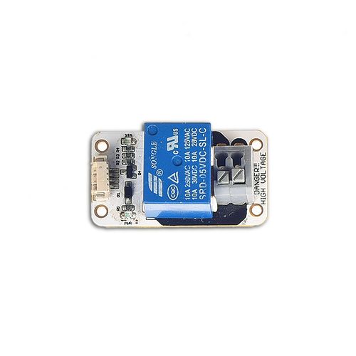
| + | *下载完毕你可以看到Relay模块上的STA灯间隔1秒钟闪烁一次,用万用表测量Relay模块上的2PIN压线端子,可以看到2PIN端子也是间隔1秒钟通断一次 | ||
| − | |||
| + | <source lang="cpp"> | ||
| + | const int Relay = 6; // the number of the LED pin | ||
| + | void setup() { | ||
| + | pinMode(Relay, OUTPUT); | ||
| + | } | ||
| + | void loop() { | ||
| + | digitalWrite(Relay, HIGH); | ||
| + | delay(1000); | ||
| + | digitalWrite(Relay, LOW); | ||
| + | delay(1000); | ||
| + | } | ||
| + | </source> | ||
| + | <br> | ||
| + | ---- | ||
| + | <p style="color: #333333;font-size:135%">'''文档'''</p> | ||
| + | *传感器CAD图纸:'''[[File:Sensor_CAD.zip]]''' | ||
| + | <br> | ||
| + | ---- | ||
| + | <br> | ||
| + | <p style="color: #333333;font-size:135%">'''相关教程'''</p> | ||
| + | [[智能温控电风扇]]<br> | ||
| + | <br> | ||
| + | ---- | ||
| + | <br> | ||
| + | <p style="color: #333333;font-size:135%">'''Q&A'''</p> | ||
| + | <br> | ||
| − | + | ---- | |
| − | + | <br> | |
| − | + | <p style="color: #333333;font-size:135%">'''历史'''</p> | |
| − | + | <br> | |
| − | + | <br> | |
| − | + | ---- | |
| − | + | <br> | |
| − | + | <p style="color: #333333;font-size:135%">'''图库'''</p> | |
| − | + | {| border="0" cellpadding="10" width="100%" | |
| − | + | |- | |
| − | + | |width="50%" valign="top" align="left"| | |
| − | + | [[file: Microduino-Relay-F.JPG|500px|center]] | |
| − | = | + | |width="50%" valign="top" align="left"| |
| − | + | [[file: Microduino-Relay -b.JPG|500px|center]] | |
| − | + | |} | |
| − | |||
| − | |||
| − | |||
| − | |||
| − | |||
| − | |||
| − | |||
| − | |||
| − | |||
| − | |||
| − | |||
| − | |||
| − | |||
| − | = | ||
| − | |||
| − | |||
| − | |||
| − | |||
| − | |||
| − | |||
| − | |||
| − | |||
| − | |||
| − | |||
| − | == | ||
| − | |||
| − | |||
| − | |||
| − | |||
| − | [[file: Microduino-Relay-F.JPG| | ||
| − | |||
| − | [[file: Microduino-Relay -b.JPG| | ||
|} | |} | ||
| + | [[MCookie 传感器系列|返回Sensor界面]] | ||
| + | <br> | ||
| + | <br> | ||
2018年11月21日 (三) 09:10的最新版本
| |
|
| 原边输入 | 5V |
| 副边输出 | 10A 250VAC/10A 30VDC |
| 接口 | D2~D13,A0~A7 |
| 接口 | 1.27mm间距的4Pin座 |
| 特色 | 可隔离控制高电压、大电流信号,体积小,易安装 |
引脚
|
编程手册
您可通过Getting Started了解使用Arduino IDE编程控制模块。
普通用法
- 1、将核心模块和传感器接口模块堆叠在电池盒模块上。
- 2、将继电器传感器通过排线接到传感器接口模块的6/7管脚上。
- 3、将USB连接线一段插入电池盒模块,另一端连接PC电脑,并打开电池盒模块的电源开关。
- 下载完毕你可以看到Relay模块上的STA灯间隔1秒钟闪烁一次,用万用表测量Relay模块上的2PIN压线端子,可以看到2PIN端子也是间隔1秒钟通断一次
const int Relay =  6;      // the number of the LED pin

void setup() {
  pinMode(Relay, OUTPUT);
}

void loop() {
  digitalWrite(Relay, HIGH);
  delay(1000);
  digitalWrite(Relay, LOW);
  delay(1000);
}
文档
- 传感器CAD图纸:文件:Sensor CAD.zip
相关教程
Q&A
历史
图库


