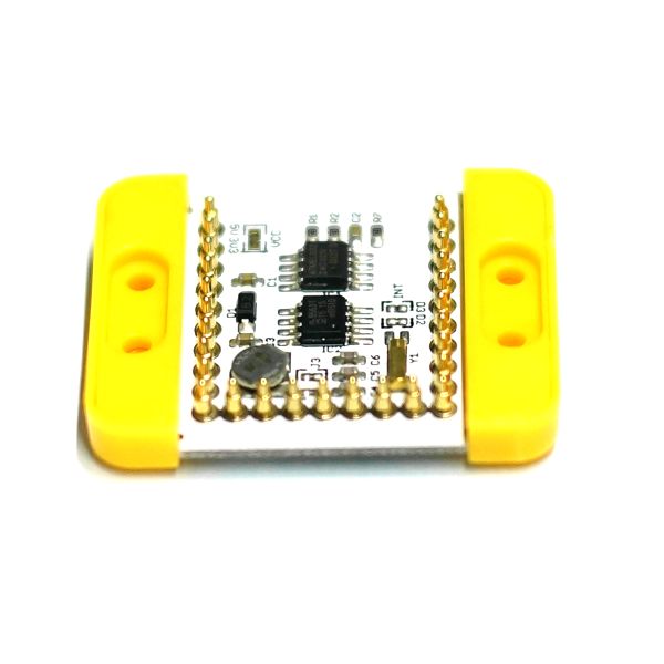
MCookie-RTC
1304410487@qq.com(讨论 | 贡献)2015年10月14日 (三) 04:41的版本 (Created page with "{{Language|mCookie-RTC}} {| style="width: 800px;" |- | 400px|thumb|right|mCookie-RTC mCookie-RTC is a clock module adopting IIC interface communi...")
| Language | English |
|---|
|
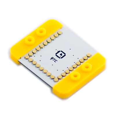
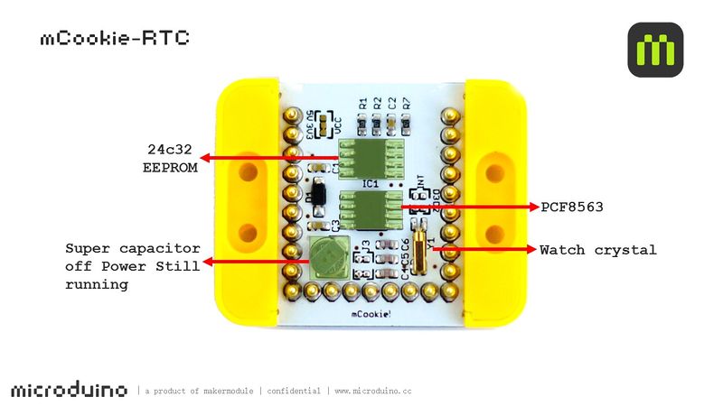
mCookie-RTC is a clock module adopting IIC interface communication, which can acquire time. With an onboard capacitor, RTC module can keep timing for several times after power disconnected.
目录Features
Specification
DocumentDevelopmentApplicationDetect Power-down Time Duration#include <Wire.h>
#include <Rtc_Pcf8563.h>
//init the real time clock
Rtc_Pcf8563 rtc;
void setup()
{
Serial.begin(9600);
settime(15, 8, 10, 4, 15, 57, 36);//Year, month, day, week, hour, minute and second
}
void loop()
{
//both format functions call the internal getTime() so that the
//formatted strings are at the current time/date.
Serial.println("CODE_1:");
Serial.print(rtc.formatDate());//Acquire data
Serial.print(" ");
Serial.println(rtc.formatTime());//Acquire time
Serial.println("CODE_2:");
Serial.print("20");
Serial.print(rtc.getYear());//Acquire year
Serial.print("/");
Serial.print(rtc.getMonth());//Acquire month
Serial.print("/");
Serial.print(rtc.getDay());//Acquire day
Serial.print(" ");
Serial.print(rtc.getHour());//Acquire hour
Serial.print(":");
Serial.print(rtc.getMinute());//Acquire minute
Serial.print(":");
Serial.println(rtc.getSecond());//Acquire second
delay(1000);
Serial.print("\r\n");
}
void settime(int _year, int _month, int _day, int _week, int _hour, int _min, int _sec)
{
//clear out the registers
rtc.initClock();
//set a time to start with.
//day, weekday, month, century(1=1900, 0=2000), year(0-99)
rtc.setDate(_day, _week, _month, 0, _year);
//hr, min, sec
rtc.setTime(_hour, _min, _sec);
}
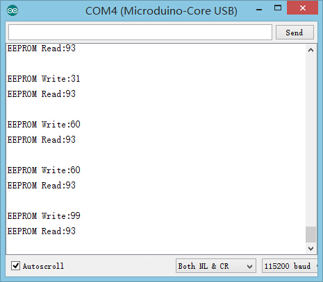
Test EEPROM Read/Write#include <EEPROM.h>
long randNumber, data; //Define random number using the name of data
//EEPROM configuration
#define EEPROM_write(address, p) {int i = 0; byte *pp = (byte*)&(p);for(; i < sizeof(p); i++) EEPROM.write(address+i, pp[i]);}
#define EEPROM_read(address, p) {int i = 0; byte *pp = (byte*)&(p);for(; i < sizeof(p); i++) pp[i]=EEPROM.read(address+i);}
//Define EEPROMdata
struct config_type
{
int EEPROMdata;
};
void setup()
{
Serial.begin(115200);
/*EEPROM read evaluation*/
config_type config_readback;
EEPROM_read(0, config_readback);
data = config_readback.EEPROMdata;
}
void loop()
{
randNumber = random(10, 100);//Random function: The values of randNumber change from 10 to 99.
delay(1000);//Rrefresh one time every second
if (randNumber != data) //Judge if EEPROM data is changed, if yes, then write in.
eeprom_write();//EEPROM write function
Serial.print("EEPROM Write:");
Serial.println(randNumber);
Serial.print("EEPROM Read:");
Serial.println(data);
delay(1000);
Serial.println("");
}
//=======================EEPROM Write Function===========================//
void eeprom_write()
{
config_type config; // Define config and its content
config.EEPROMdata = randNumber;
EEPROM_write(0, config); //Save "config" to EEPROM and write address 0
}
PurchasePicture |
